Report of the 90-day study on human exploration of the Moon and Mars
Robotic Missions
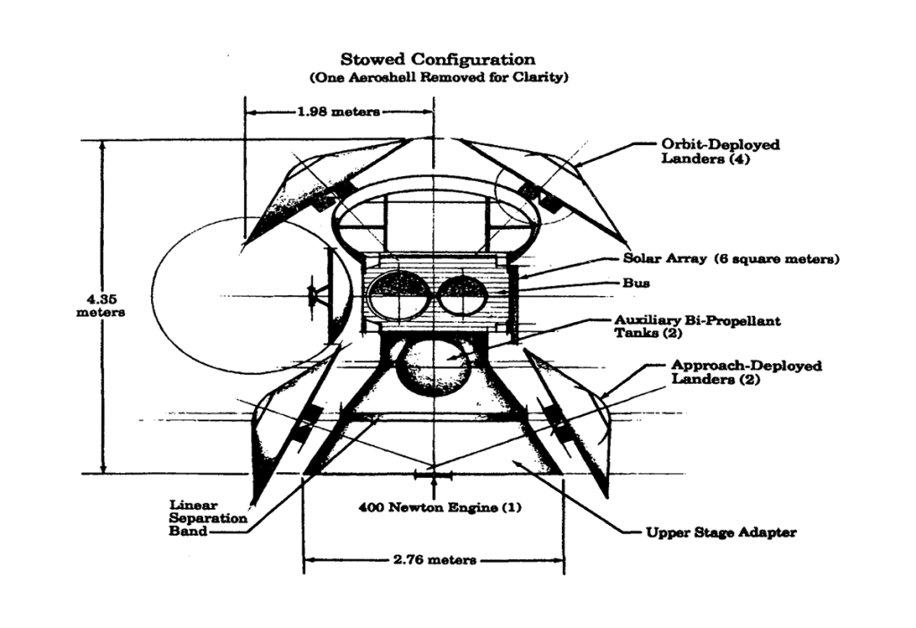
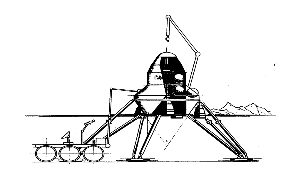
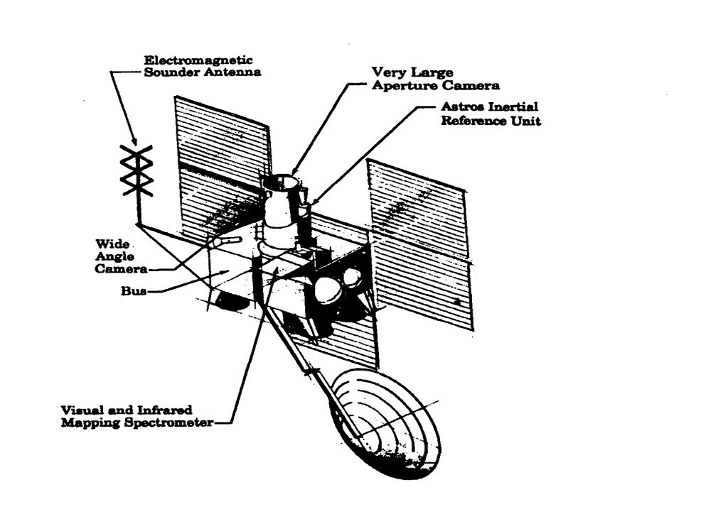
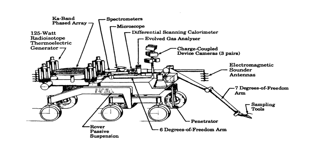
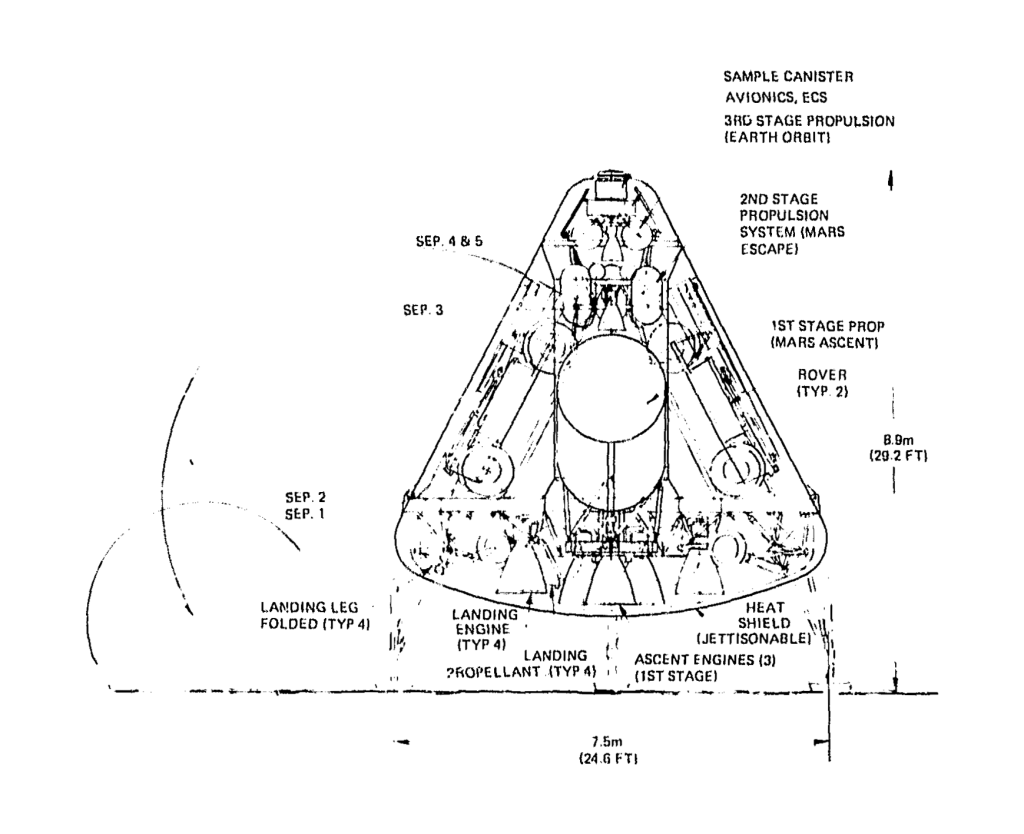
Mars Global Network Mission Vehicle Concept Using LandersSample Return Vehicle with Local RoverMars Site Reconnaissance Orbiter ConceptLong Range Mars Rover
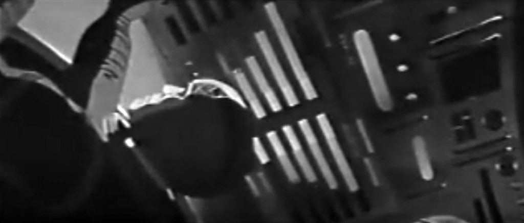
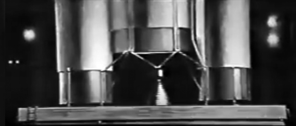
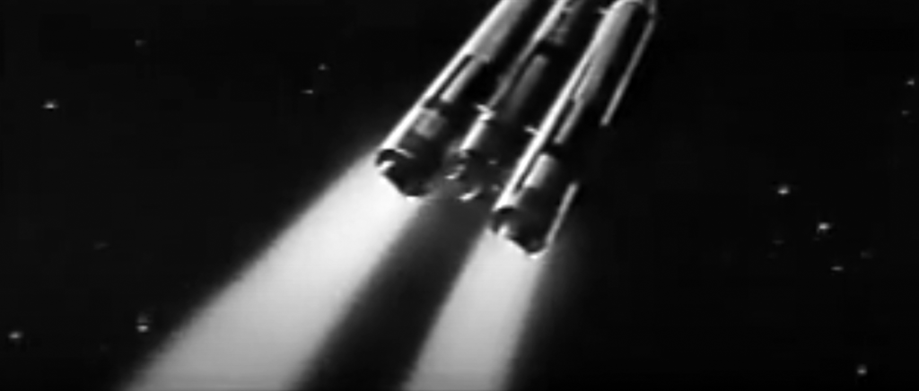
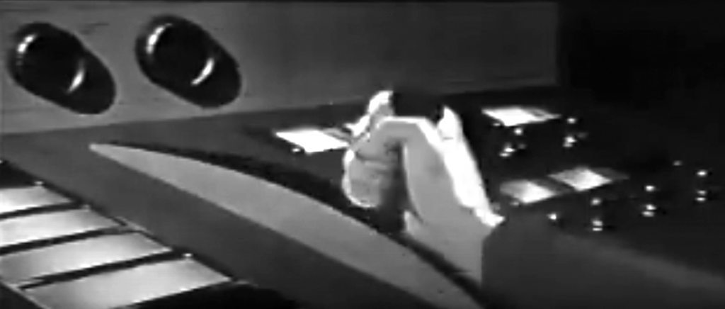
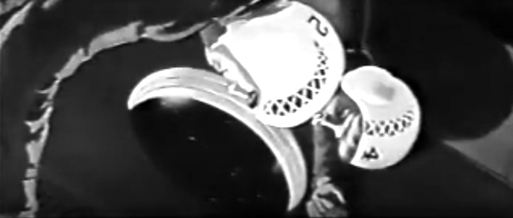
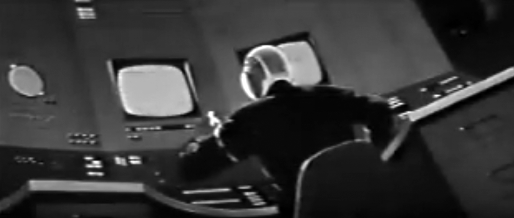
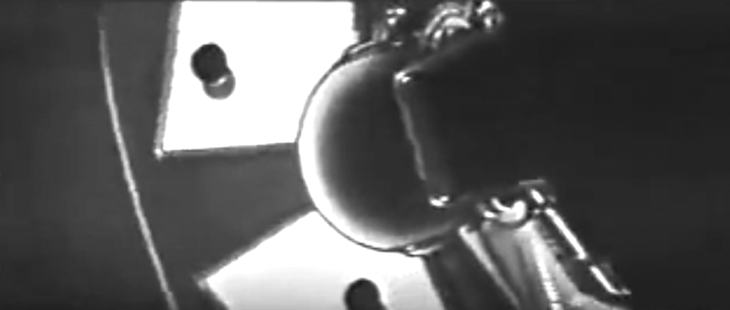
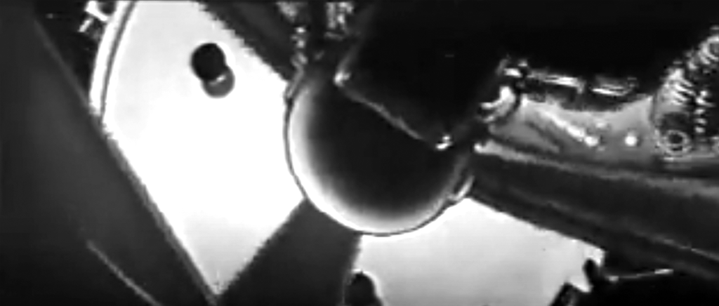
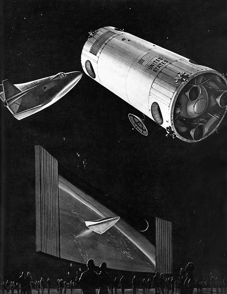
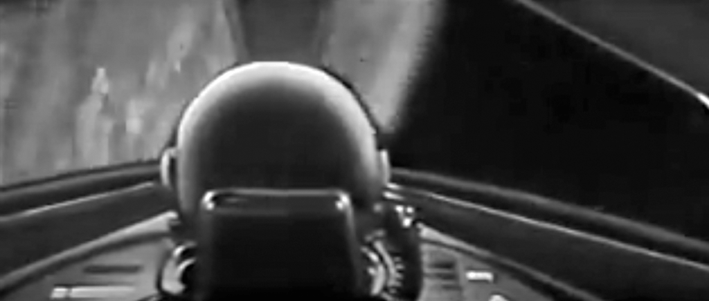
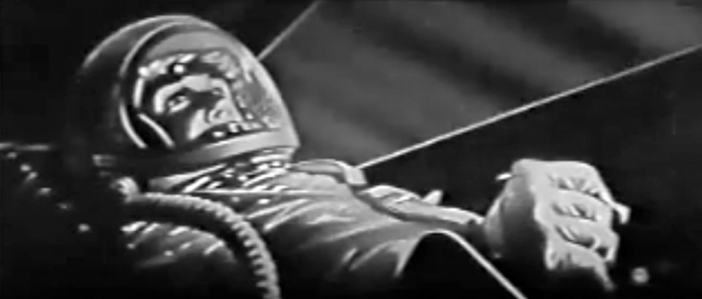
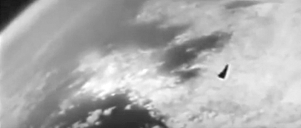
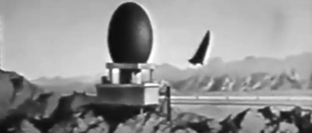
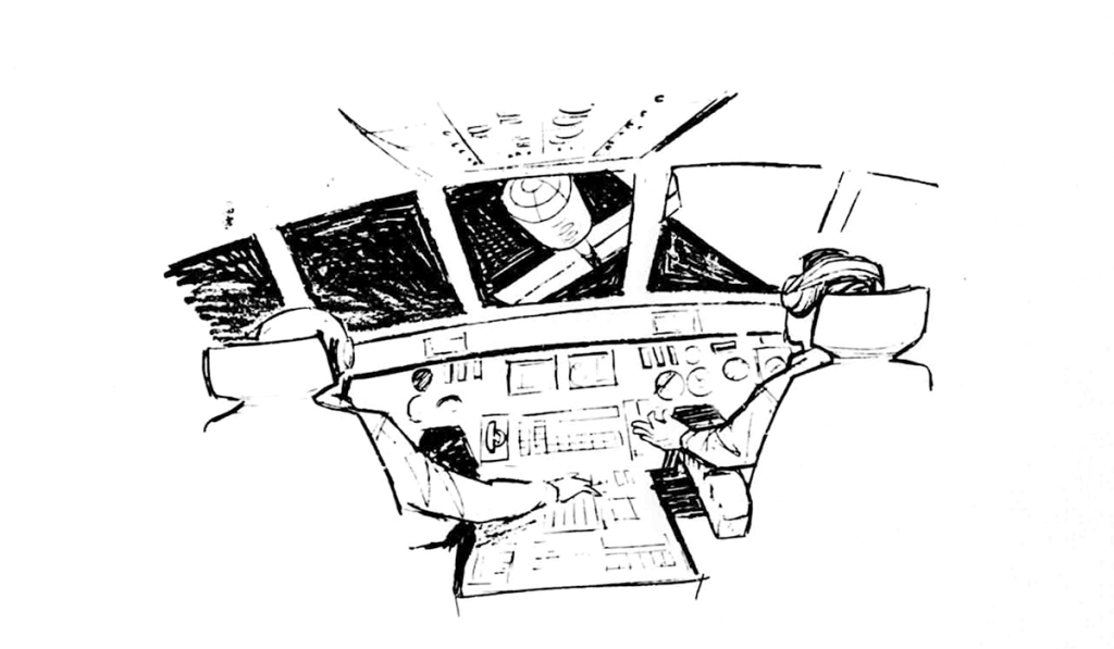
If you were lucky enough to attend the New York 1964 World’s Fair, one of the treats was a documentary film presentation at the Science Pavilion. Rendezvous in Space, a film about the future of space exploration was directed by Frank Capra, and features a cast of notable Hollywood voice actors including Mel Blanc, June Foray, and Alan Reed. You can watch the complete film here.
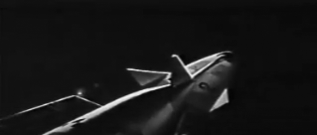
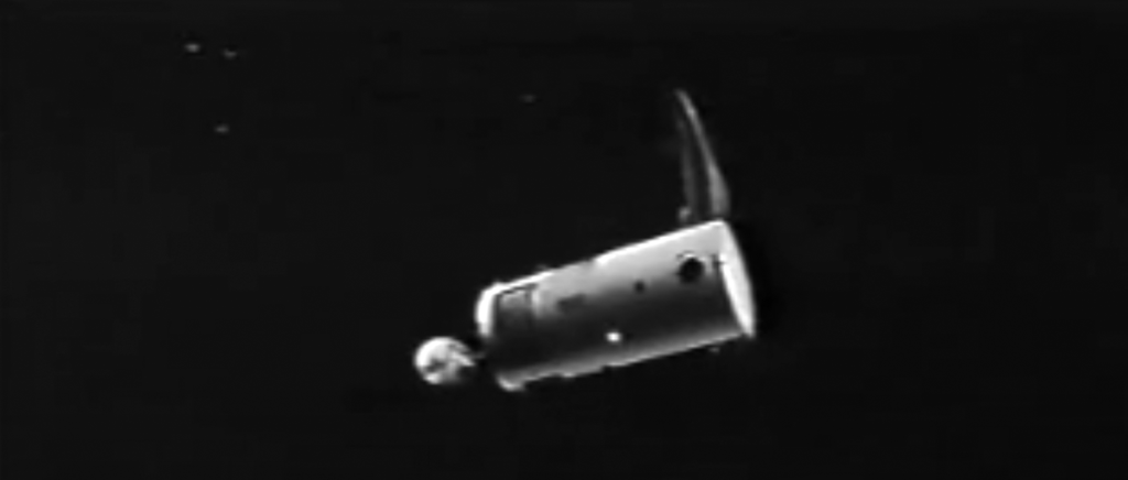
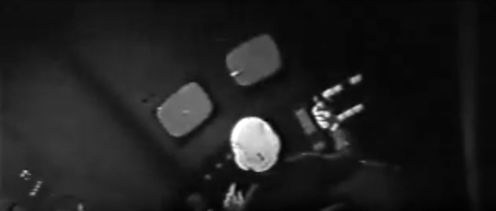
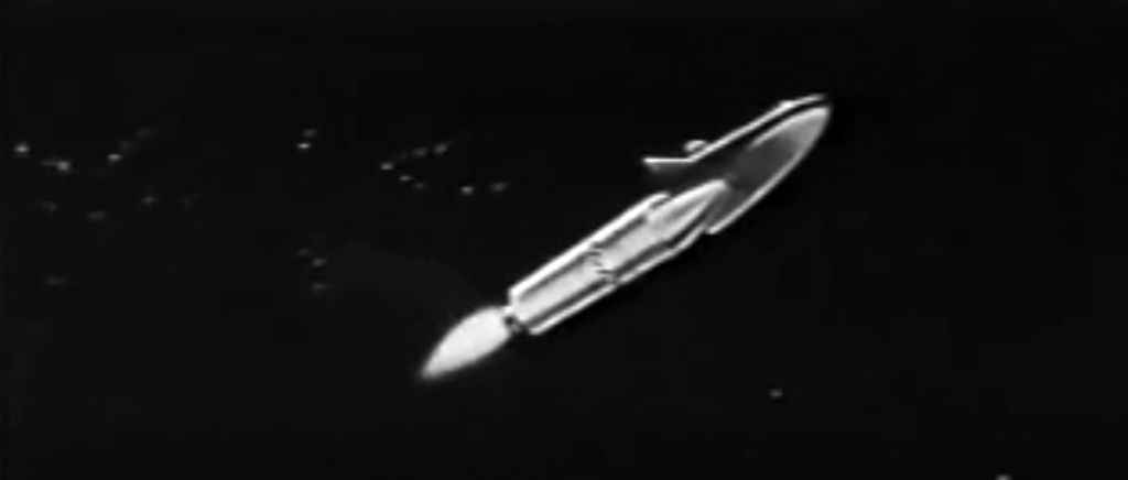
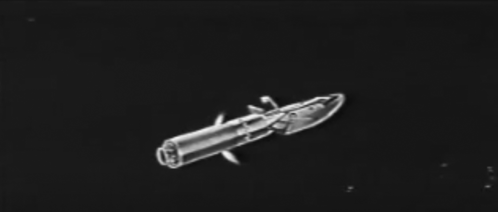
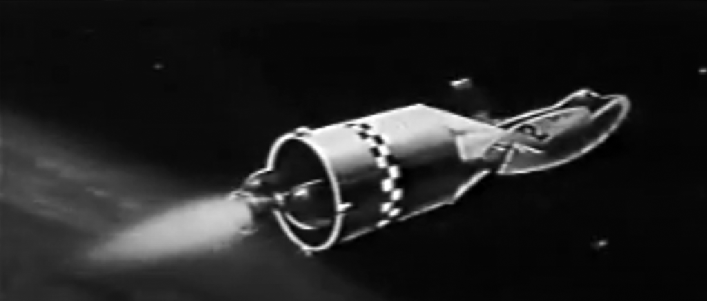
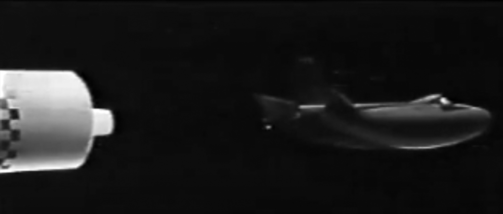
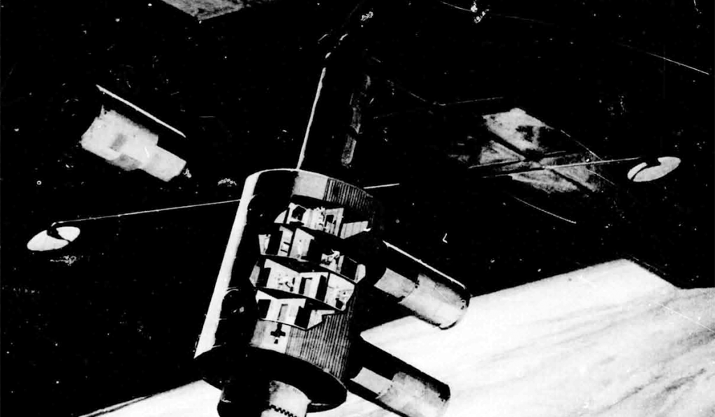
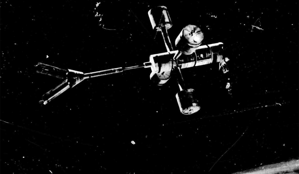
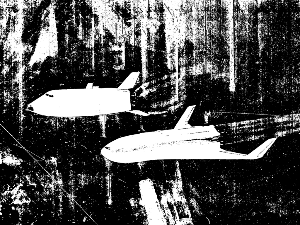
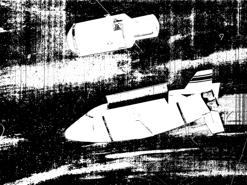
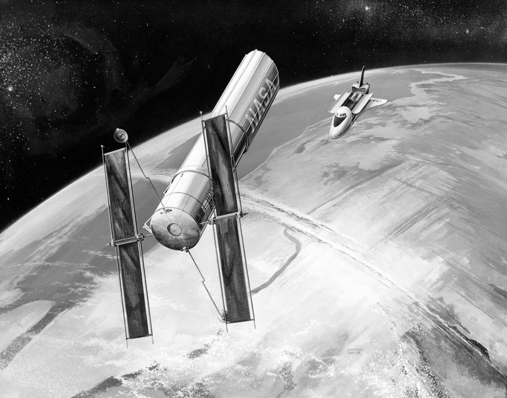
At this point, the screen goes black with only audio, as the audience’s gaze is directed above to the full-sized models of the Space Taxi docking with the station, which would have looked something like this:
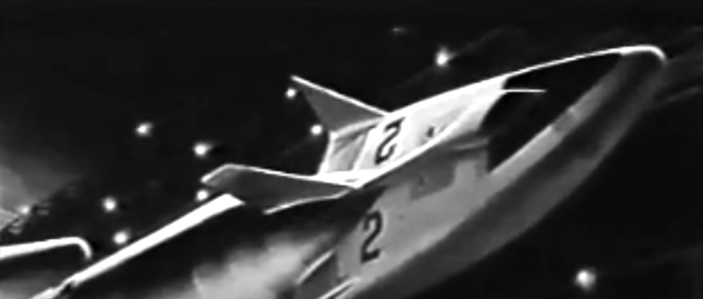
I imagine it was quite the spectacle. Anyway, after that it’s time for home.
Image credit: Martin Marietta Image source: Numbers Station
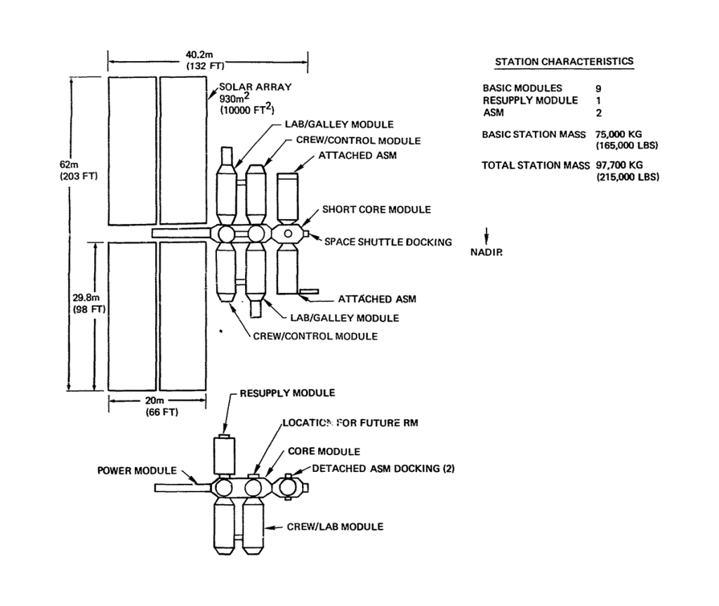
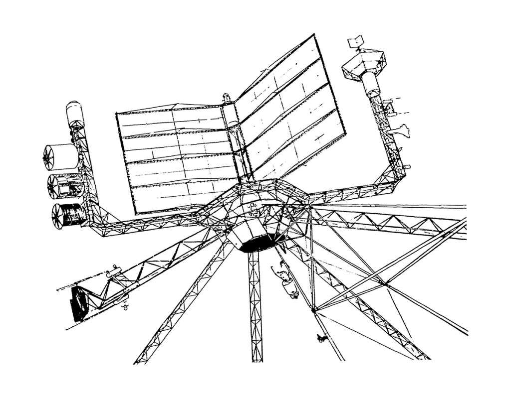
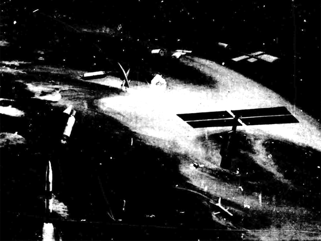
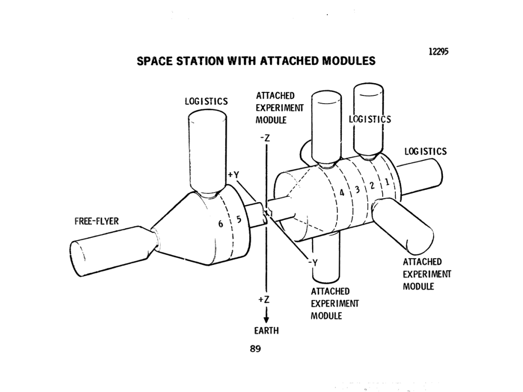
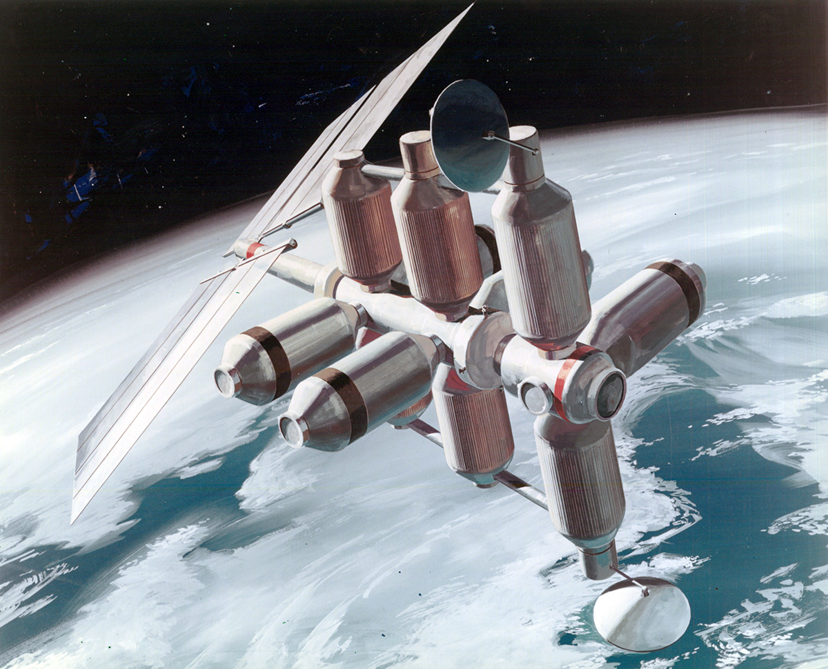
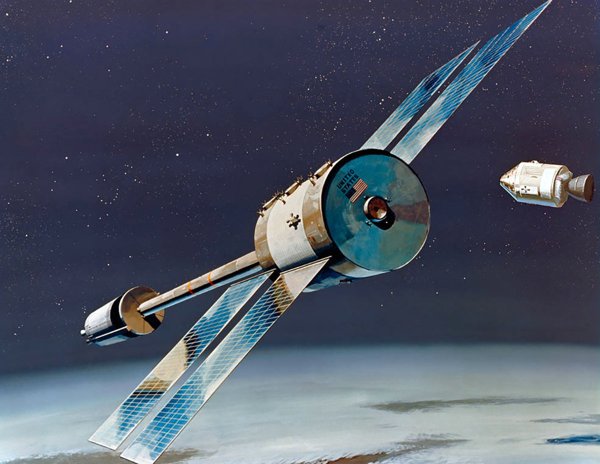
This chart depicts the 12-man Space Station as currently conceived out of the on-going Phase-B Space Station Program Definition activities. The concept shows four decks in the core module, two attached experiment modules, and a detached experiment module floating in the immediate proximity of the Station. The solar arrays represent just one possible means of generating the 25 kilowatts of power required by the Space Station. The core module is 33 feet in diameter and approximately 50 feet in length and is launched by the INT-21 launch vehicle (S-IC/S-II) from one of the Saturn-V launch pads already in existence at Kennedy Space Flight Center. The Space Station is designed to operate in a low earth orbit at an altitude of 200 to 300 nautical miles and a nominal inclination of 55 degrees. Current planning indicates that this Space Station could be launched late in Calendar Year 1977 and could operate for several years in the 1980’s.
Space Base Concept
This chart shows an artist’s concept of the 50-man Space Base. The crew modules used in the Space Base can be evolved from the 12-man Space Station module. The concept shows the two nuclear reactors which provide electrical of up to 100 kilowatts, joined to the zero-g hub. The Space Base, which operates in low earth orbit during the decade of the 1980’s, is a multipurpose research and development facility to which scientist and other users can be transported by the Shuttle and which will support these people they are undertaking their particular activities in orbit.
Planetary Space Vehicle Concept
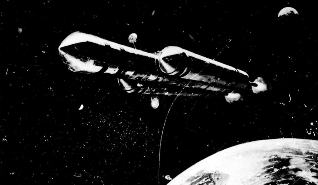
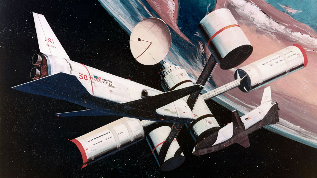
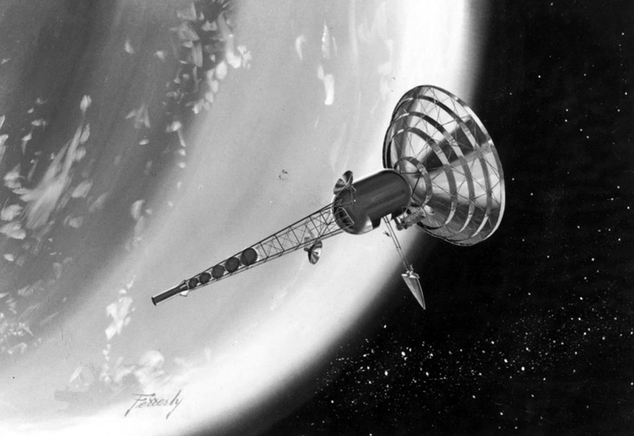
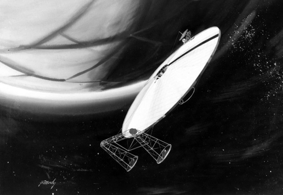
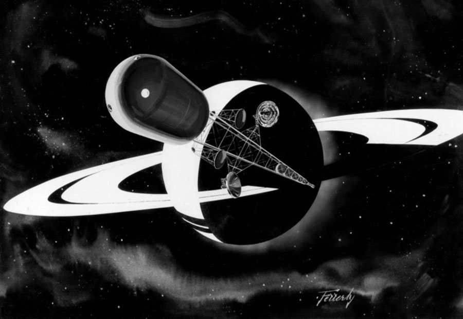
The Phase-B Space Station Program Definition activities have also considered the evolution of the Space Station module into the manned planetary mission module. Shown here is an artist’s concept of the manned planetary vehicle as it leaves the earth on the transplanetary mission in the mid – to the late – 1980’s.
Nuclear propulsion using the Nerva-1 type engines provides the primary propulsion for this deep space mission. The primary mission under consideration is onward which will accomplish a Mars landing using the Mars orbital rendezvous technique and a swing by Venus on the return leg to earth. Depending on the mission opportunity, the total mission duration is between one and two years. The 12-man earth orbital has a large number of the features required by a planetary mission module; and is desirable, where possible, to shape the Space Station program in such a way that it represents the maximum step along the road to this mission of the future, while at the same time it does not compromise the Station for its primary earth-orbit mission objectives.
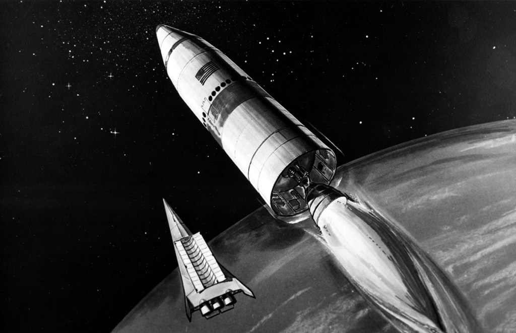
Space Shuttle
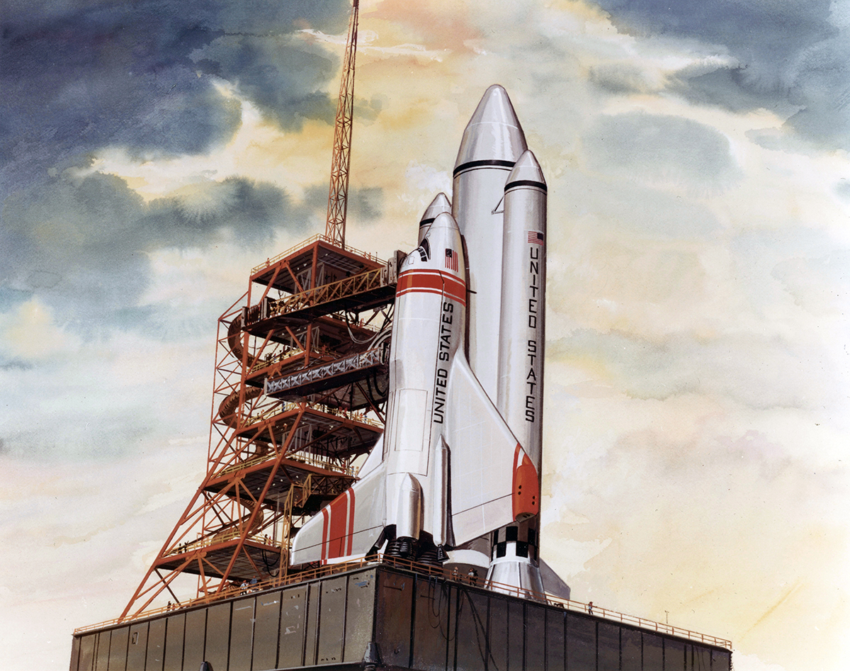
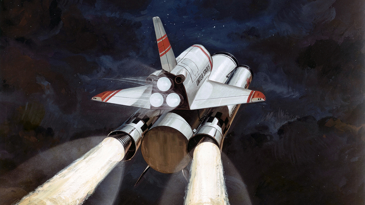
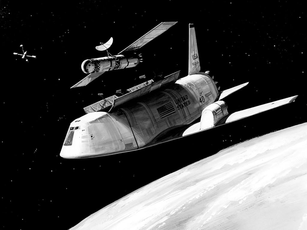
During the late 50’s and the decade of the 60’s, the limitations of technology required that the transport of man and other payloads to earth orbit be accomplished by a multistage expendable launch vehicle. as the level of activities in earth orbit increases and as the number of crew and amount of cargo requirements to be transported to earth-orbit increases, the desire for a much lower cost and more convenient means of transporting personnel and material to orbit is obviously required. The two-stage, all-reusable shuttle depicted here is one means of accomplishing this. Whereas the development of a system like this type requires the dedication of considerable resources over several years, the tremendous increase in convenience and economy represents the essential breakthrough necessary for a viable space program.
Space Station Internal Configuration
Deck 1
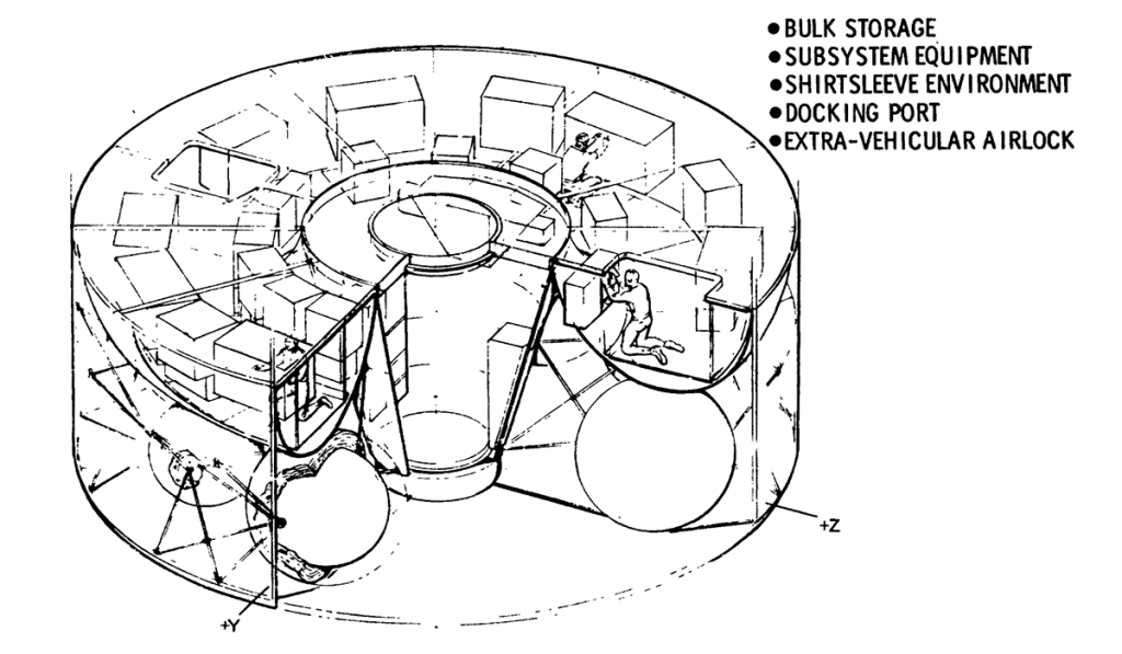
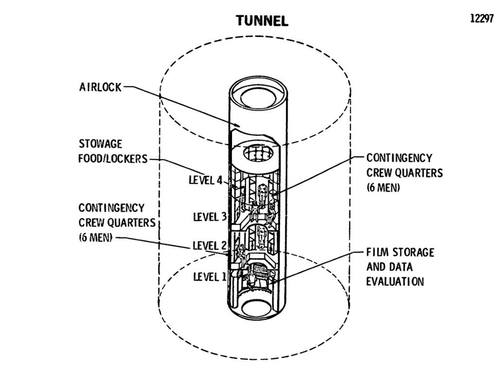
A greater detailed look at the lower torus area/tunnel in addition to the bus storage are shoes the large, extravehicular airlock with the docking port at the outer end. This area is a completely shirt-sleeve environment. A main aisleway is utilized in the torus to allow crewmen access to the equipment mounted on both sides of the aisleway. The aisleway and equipment are structurally supported from the Deck-1 bulkhead above, which forms the ceiling of the toroidal area. Two large 4- by 5- access openings in the Deck-1 bulkhead (toroidal ceiling) provide access to the toroidal area. The lower tunnel is also utilized as an extra-vehicular airlock with a docking port at one end and pressure hatch at the other. Below the torus area are located the propellant tanks of the RCS.
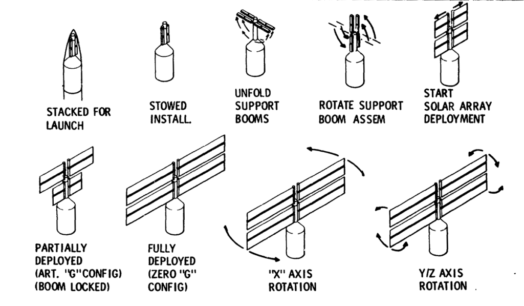
Space Station Launch Sequence
Solar Array Deployment/Sequence
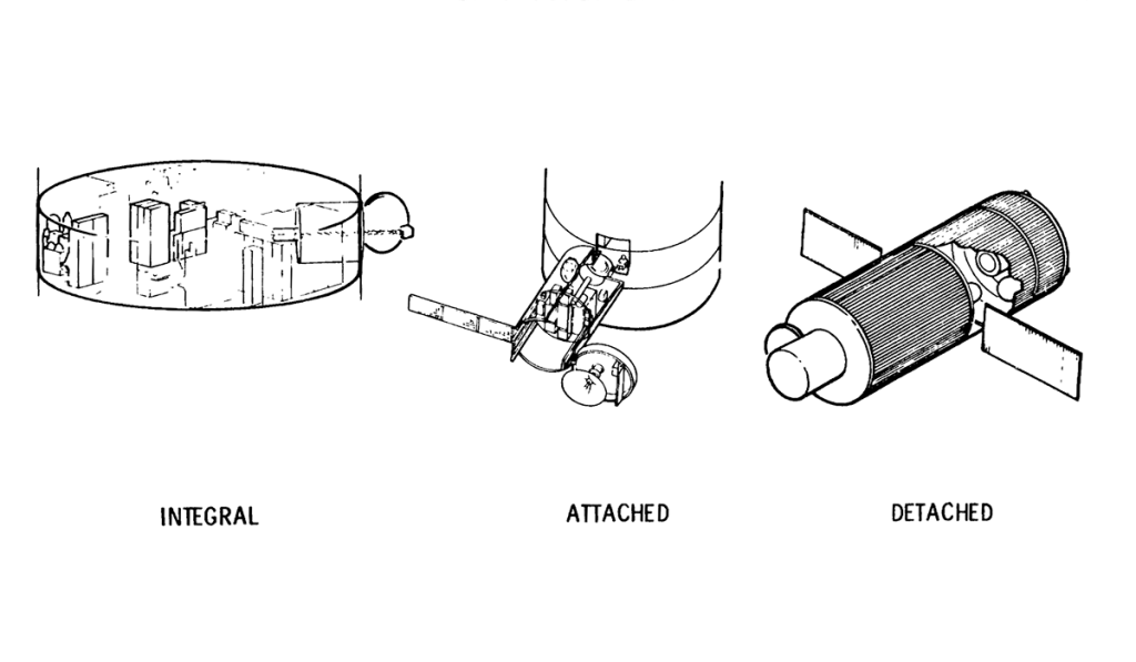
Experiment Operating Modes
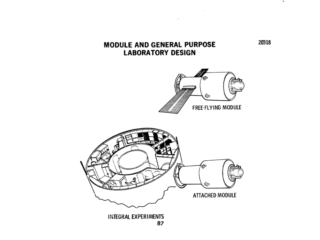
The experiments operating on the Space Station can either be accommodated integrally to the core module in a module that is attached to one of the docking ports on a semipermanent basis but which can be easily be replaced when its usefulness has expired and in detached flying-type modules which periodically rendezvous and dock with the Space Station core module for periodic module and experiment maintenance, update, film/tape reloading, etc.
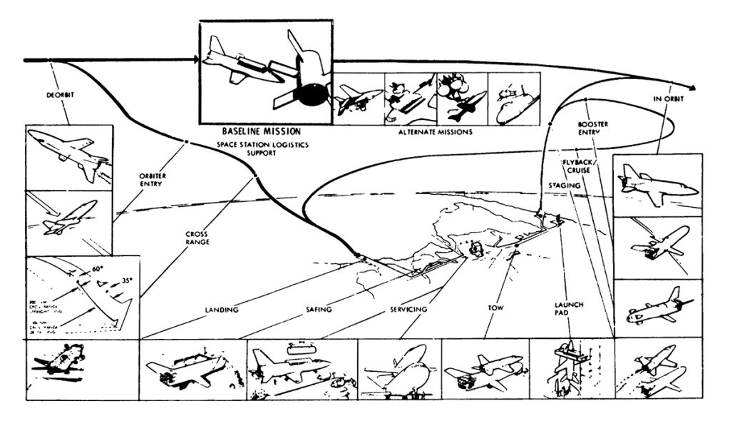
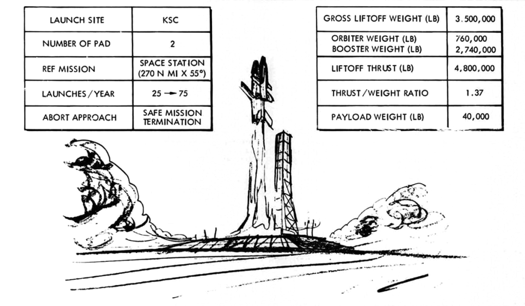
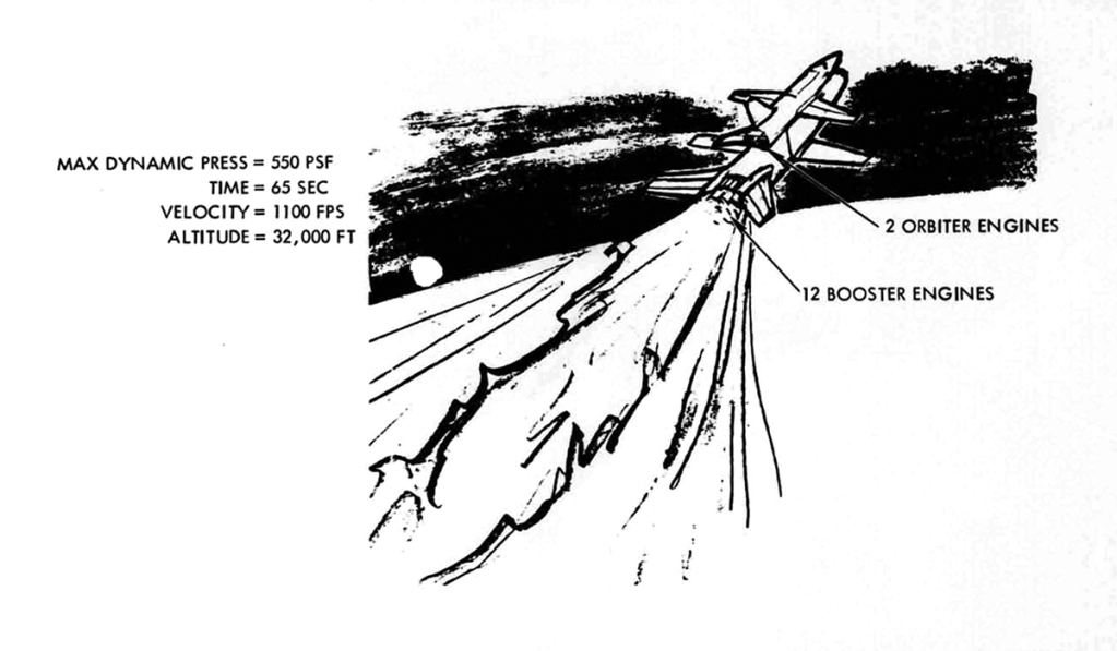
Shuttle Mission Profile
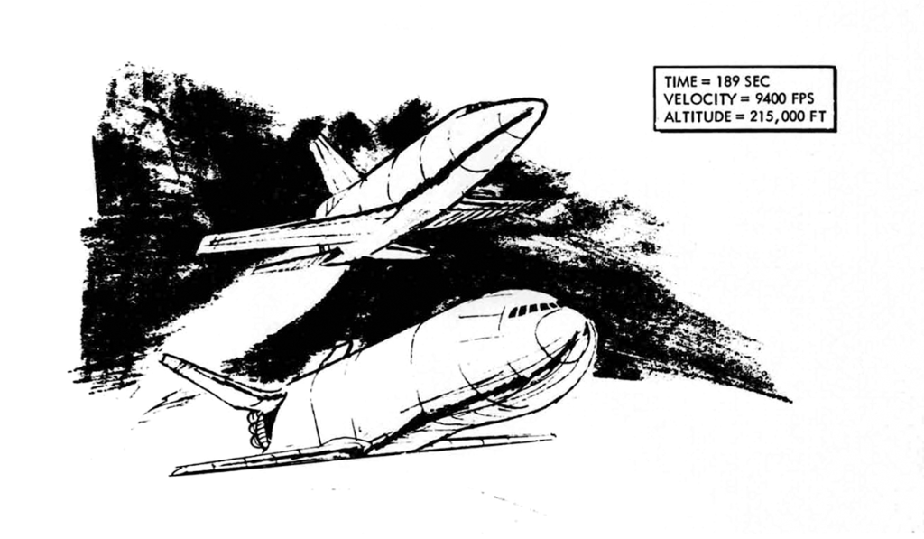
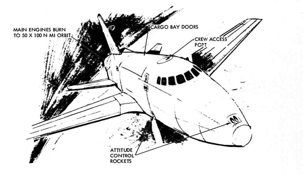
Presenting a more detailed look at the mission from launch to docking, this chart depicts the launch readiness through the max q and the subsequent staging operations, the insertion into 50 by 100 nautical-mile elliptical orbit, and the subsequent rendezvous and docking maneuvering.
Briefing to the European Space Research Organization
June 3-5 1970
Speaker: C.J. Dorrenbacher – Advance Systems and Technology
McDonnell Douglas Astronautics Company
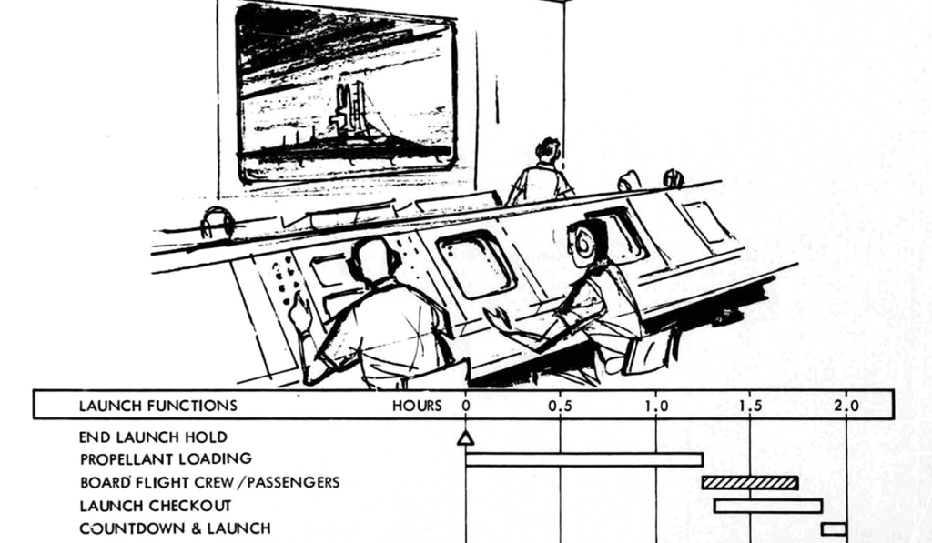
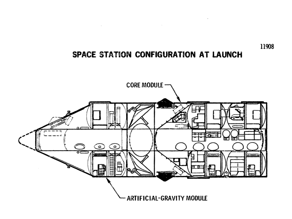
The launch vehicle places the Space Station into a 456-kilometer circular orbit at an inclination of 55 degrees. The S-II second stage is separated and deorbited into a preselected deep-ocean area. The critical systems – communications, life support, etc. – are activated and the readiness of the Space Station for manned occupancy is verified prior to committing the launch of the logistics system that will carry the Space Station crew.
The logistics system, which consists of the logistics spacecraft (or orbiter) and the crew/cargo module is launched 24 hours after the launch of the Space Station. After rendezvous some 8 hours later, the crew/cargo module separates from the logistics spacecraft and propels itself toward a docking maneuver with the Space Station. After docking, the crew enters the station, activates the remaining systems, and advises the orbiter that station operations can begin. Approximately 25 hours after initial manning, the orbiter begins its return flight to Earth.
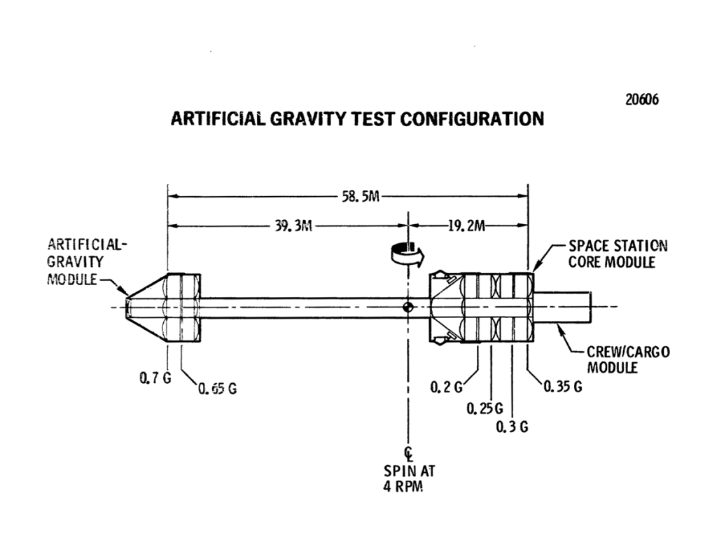
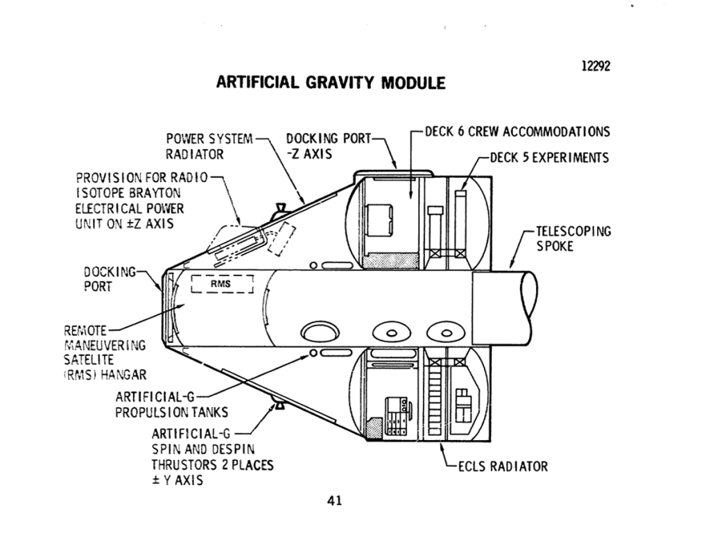
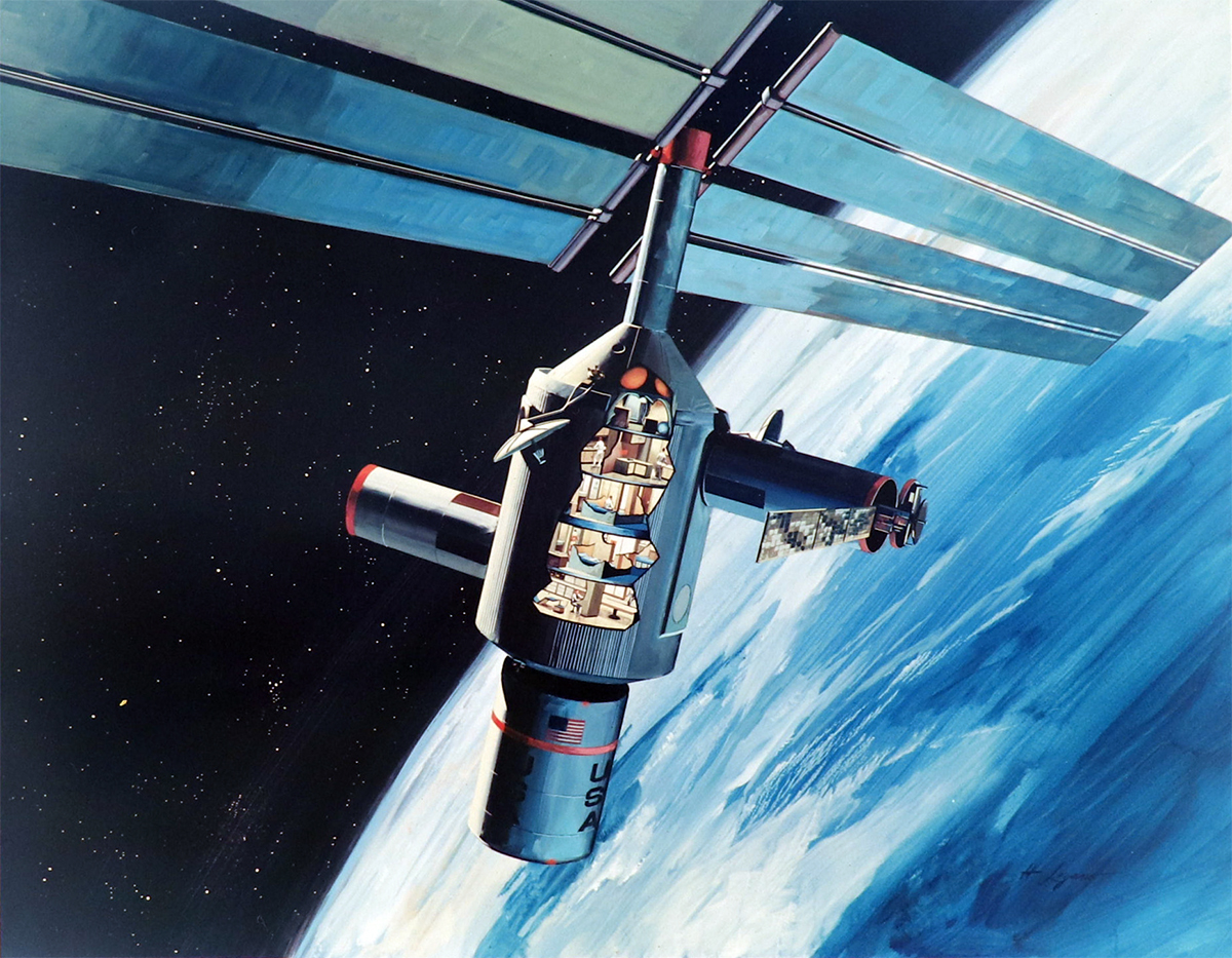
During the first month, the crew activates all systems and readies the station for artificial-gravity test operations. The artificial-gravity module is deployed on a telescoping spoke. The combined mass of the artificial-gravity module and the station is spun around the center of gravity; the resulting centrifugal force produces a simulated gravity environment. The purpose of this operation is to explore the potential benefits and problems associated with artificial gravity.
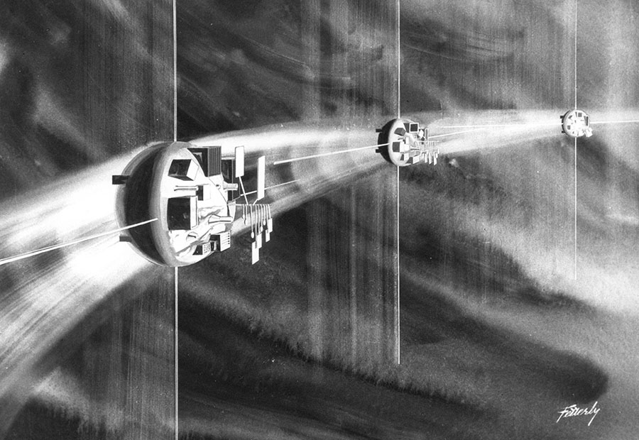
When the artificial-gravity operations are completed, the logistics system begins delivery of additional experiments contained in modules; typically the Space Station may have three or four modules attached to it while three or four modules are flying free around it. Logistics appointments become regular (nominally. every 90 days) and experiment program is in full swing.
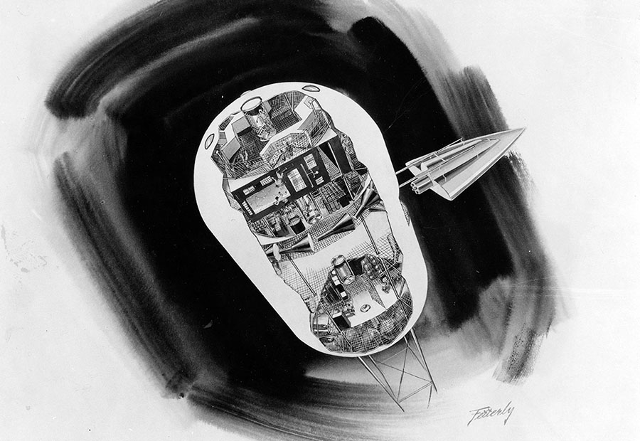
The Space Station is shown in a cutaway perspective. Equipment and activities are depicted as they would look upon completion of the outfitting of the station. The telescoping spoke is abbreviated for the purpose of this illustration.
During the 30-day artificial-gravity experiment, half the crew (six-men) occupies the deployed artificial-module. The men will live in the same environment as those remaining in the core module except that their effective gravity will be higher (0.7g) than it is in the core module. Some of the core will inhabit a zero-gravity cab located at the center of rotation; there they will duplicate certain tasks being performed in artificial gravity so the effects of the two enviroments can be compared. Of major interest is an evaluation of the effects of going to a zero-gravity environment to an artificial-gravity environment. The Space Station can repeat the artificial-gravity test as required: about five repetitions are assumed for design purposes.
The Space Station is 9.2 meters in diameter and about 34 meters. It consists of a core module. Further modular division is visible in that the core module contains two separate modules, each consisting of two decks; a third two-deck module comprises the habitable portion of the artificial-gravity module.
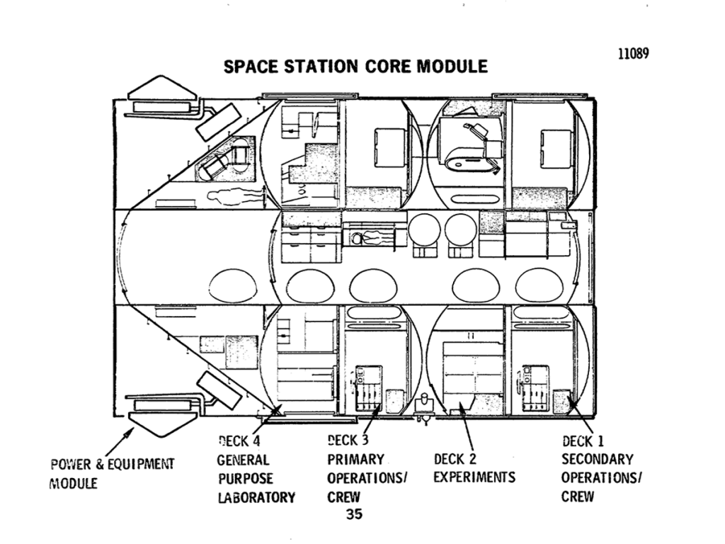
The core module contains three pressurized compartments; the compartment formed by Decks 1 and 2, the compartment formed by Decks 3 and 4, and the central tunnel. This feature ensures that a habitable environment will be available should pressure be terminated in either of the two primary compartments. The tunnel serves as the primary traffic route for men and equipment between the decks. The forward end of the core module contains the isotopes/Brayton electrical power system in an unpressurized environment and a storage compartment, which may be pressurized for access.
The core module tunnel has many functions other than that of being the main traffic artery. Contingency provisions are available should habitation of this compartment be required.
Similar to the forward half of the core module, the artificial-gravity module contains a two-deck module and a conical section containing a propulsion system to provide the spin necessary for artificial-gravity operation. This conical section also has provisions to increase the electrical power capability of the Space Station through the later addition of one or more isotope/Brayton units. Initially, Deck 6 is configured as a crew and operations facility for the artificial-gravity experiment. When the equipment used in the crew and operations facility is stowed, the volume can be converted to accommodate additional research facilities. If the need arise to accommodate a larger crew (up to 18 men), this deck can be reconverted to a crew facility. Two centrifuges occupy Deck 5.
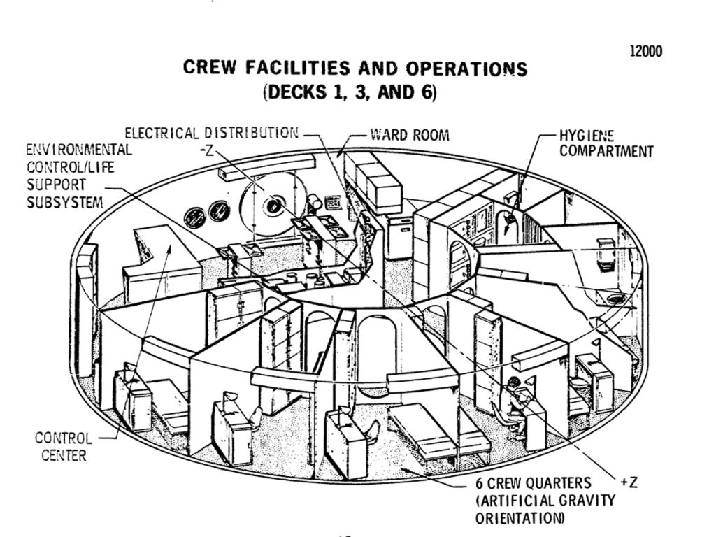
One deck in each of the three modules is configured to support the crew. Facilities on each deck are sized to provide private quarters and eating and hygiene facilities for six men. However, the life support system will accommodate the entire crew of twelve on any deck. The layout is shown for the artificial-gravity module.
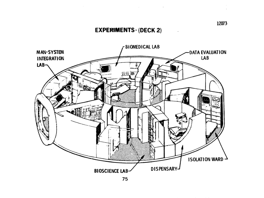
Deck 2 is dedicated to experiment activities associated with the study of various life forms in zero activity. man, animals, plants, micro organisms are all subjects for analysis. Considerations of equipment and facility commonality result in locating the dispensary and isolation ward adjacent to these laboratories.
Experiments may be accommodated either within the Space Station or in attached or free flying modules that use services provided by the Space Station. Internal experiments are either launched with the Space Station or brought up layer by the logistics system, transferred aboard, and installed; all attached and free-flying modules are delivered to orbit by the logistics system.
The Space Station contains a total of eight docking ports; these ports are of a universal design to accommodate either crew/cargo modules or attached to free-flying experiment modules. Normally, logistics modules will dock on the artificial gravity module and the aft end of the core module. The free-flying experiment modules will share the forward docking port, while all attached modules dock to the core module.
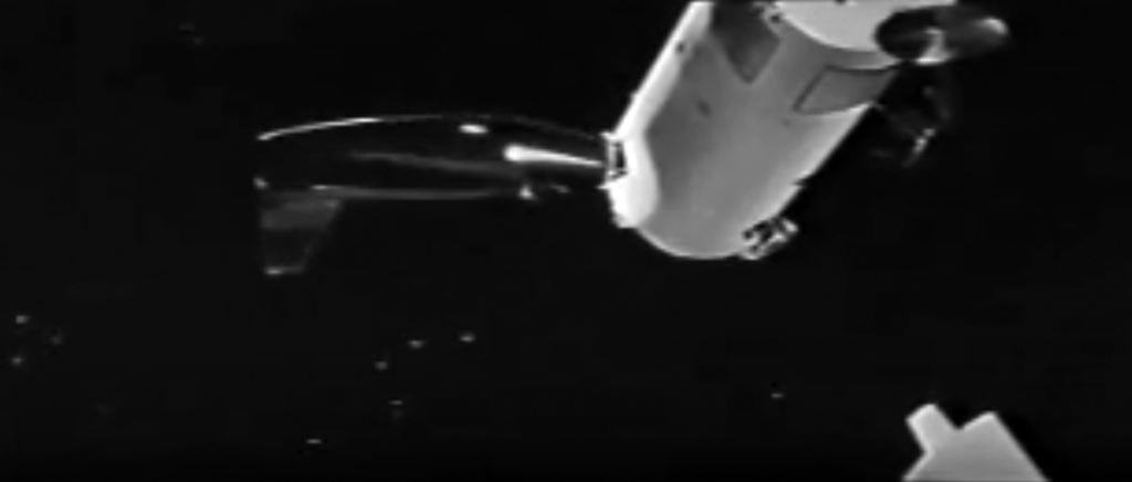
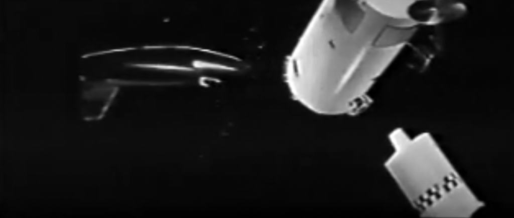
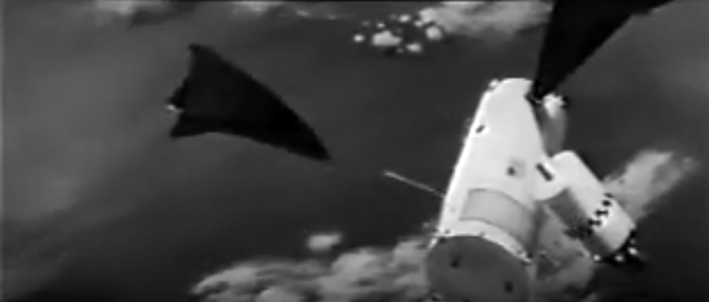
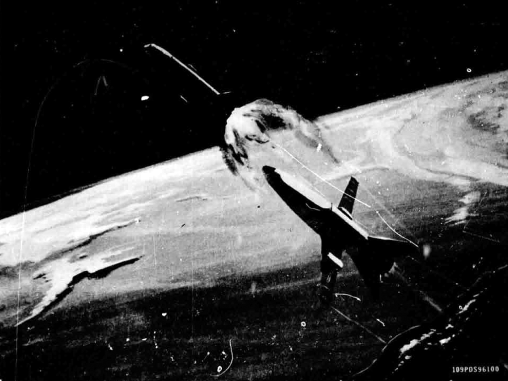
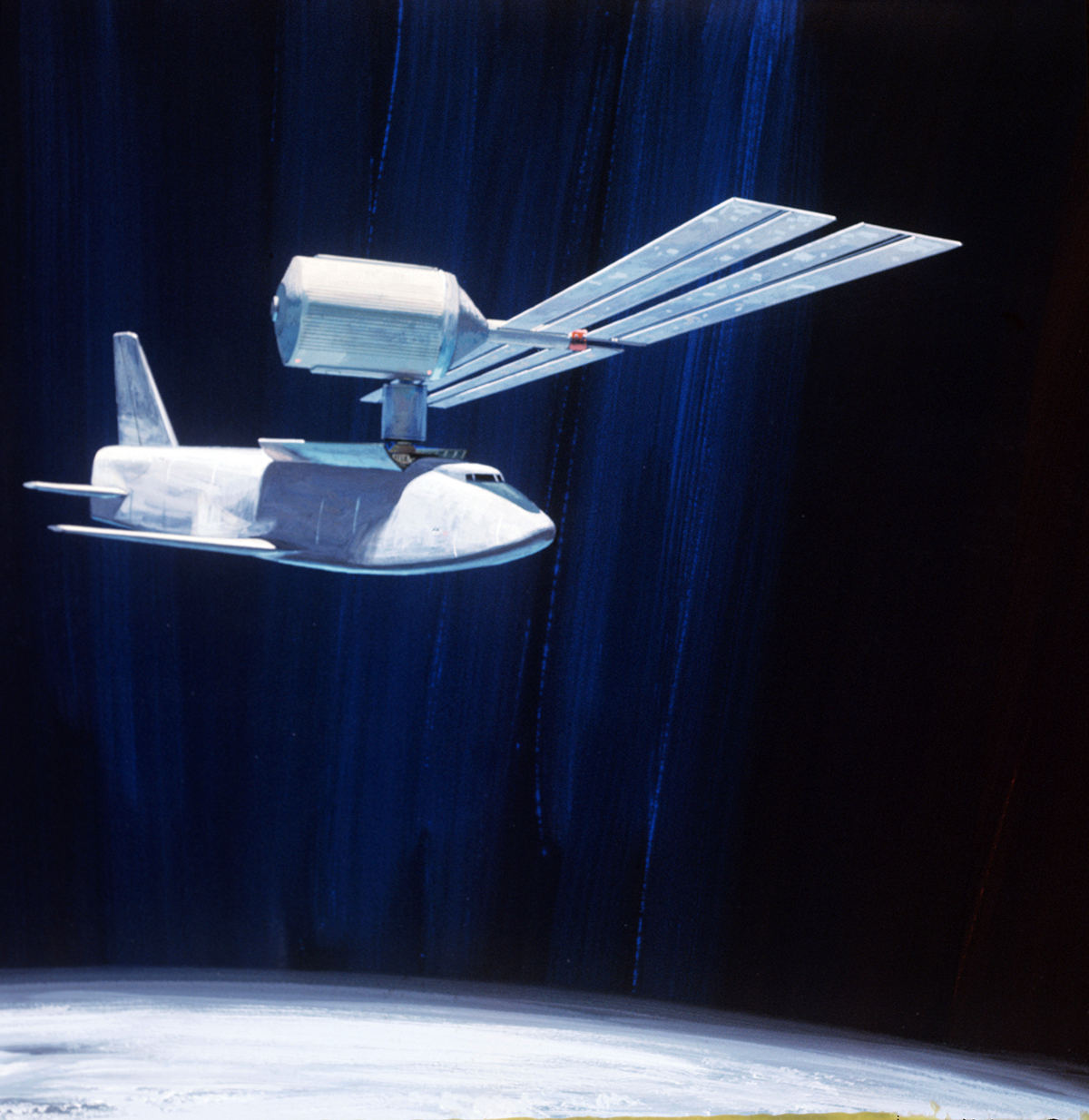
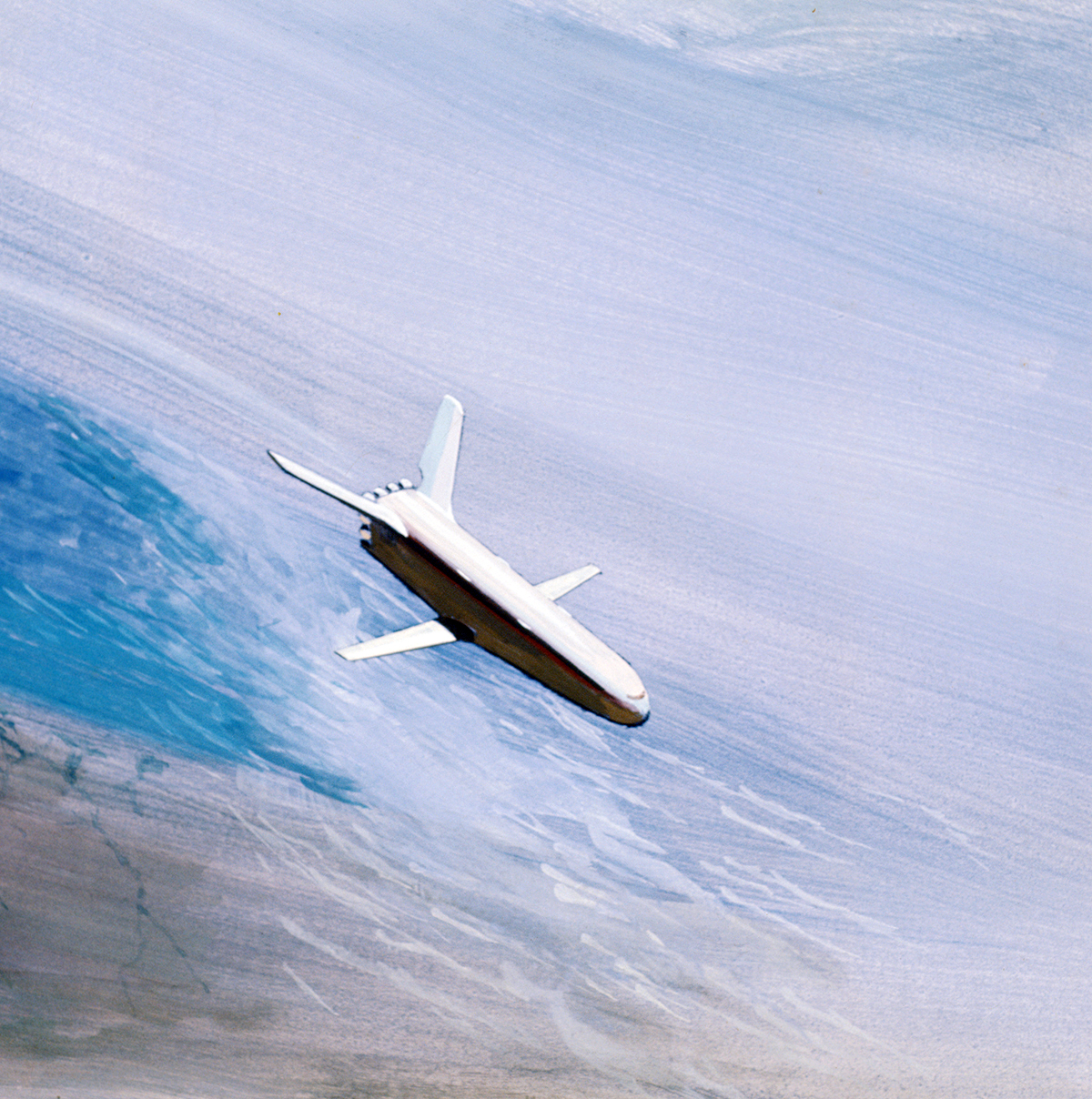
The orbiter is seen separating from the booster stage, which now prepares to return to Earth.
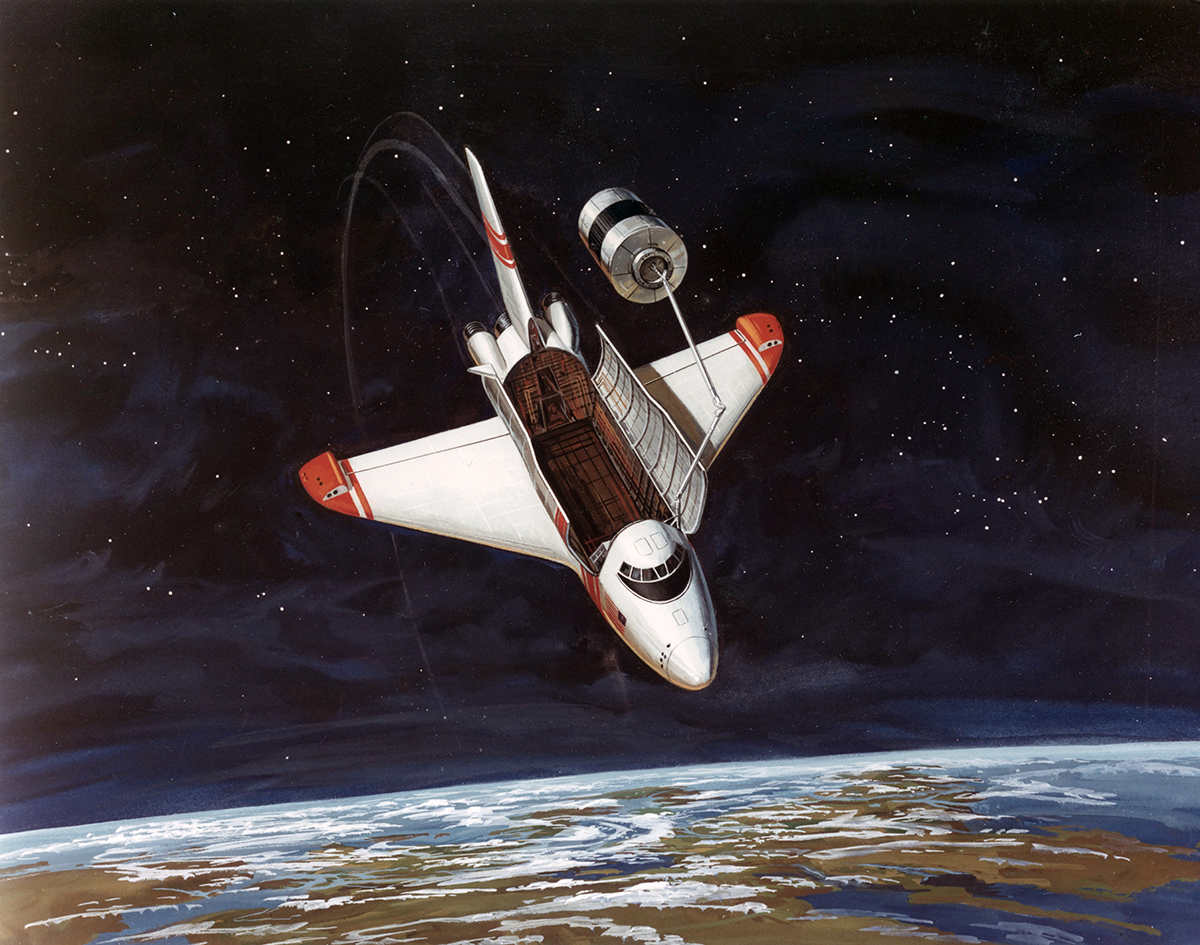
A typical payload for the logistics system is an experiment module leaving the cargo bay. Its propulsion system has ignited as it makes its guided way to the station.
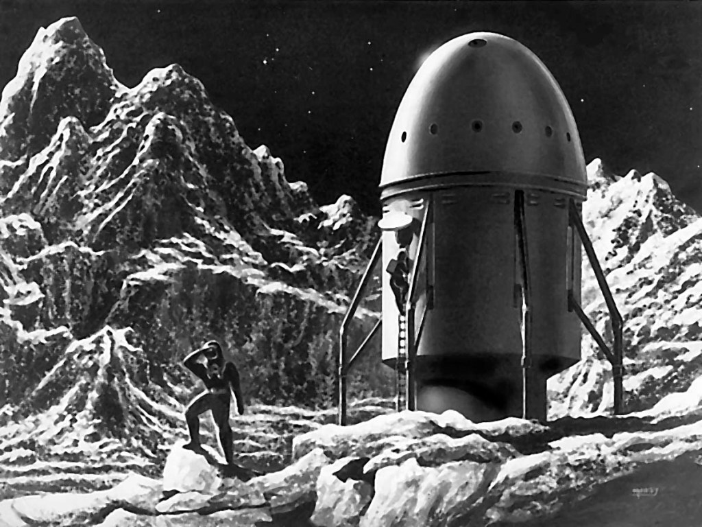
Stunning artwork by Alexander Leydenfrost prepared for a 1946 article in Collier’s Magazine
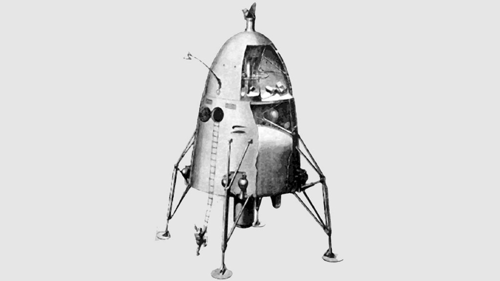
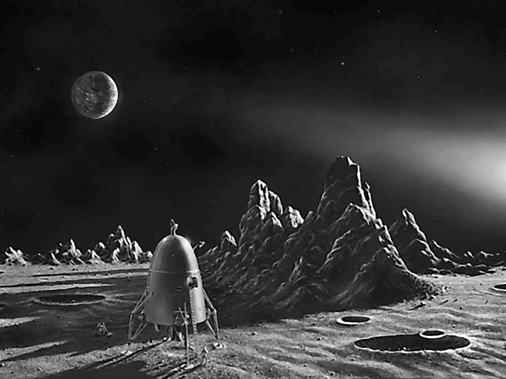
BIS Lunar Spaceship – 1938
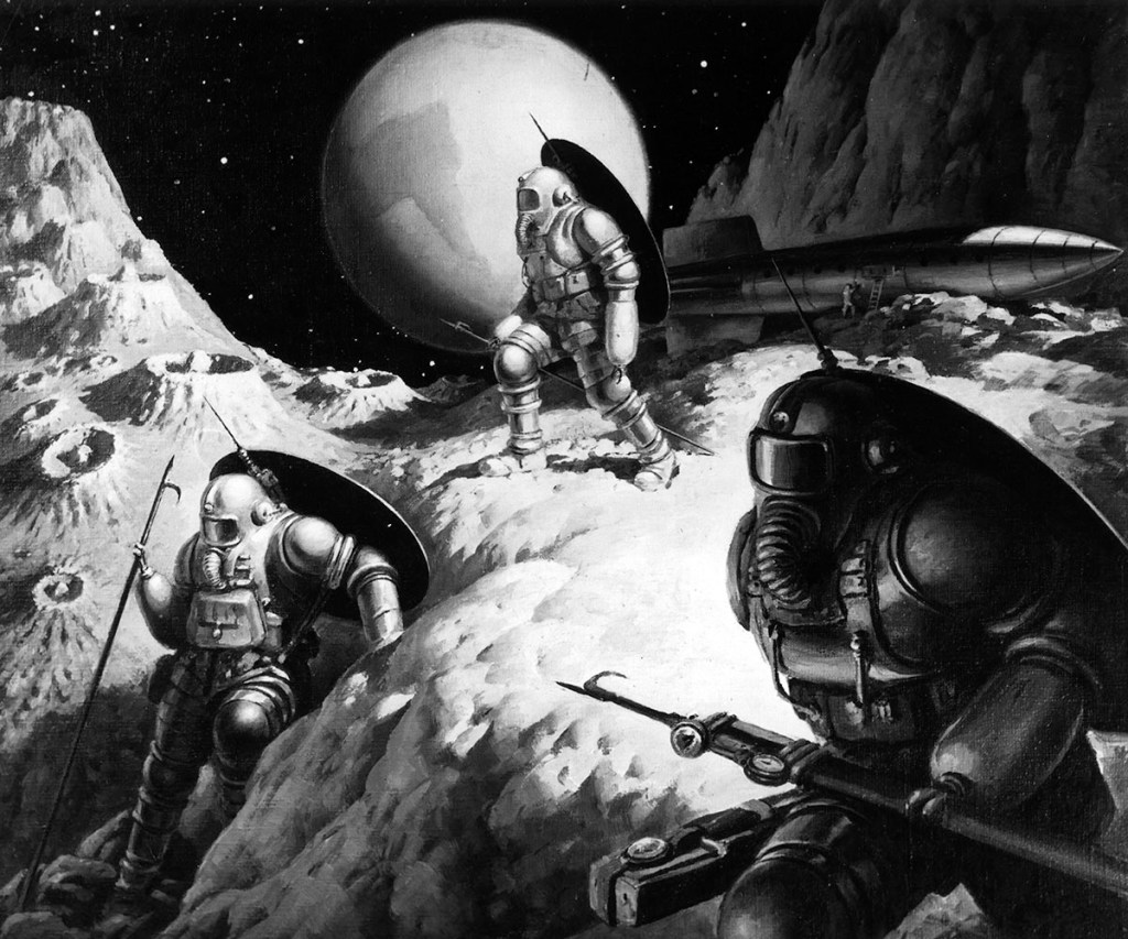
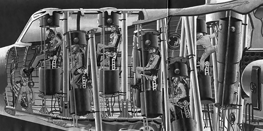
In 1938, the British Interplanetary Society Technical Committee began a study that looked at the feasibility of a lunar expedition using existing technology.
The rocket would be launched from a partially submerged caisson, ideally staged on a high-altitude lake close to the equator. High pressure steam would give the vehicle its initial boost, the first step of rockets firing immediately afterwards. Shock-absorbing legs would extend from the base of the crew module for the lunar landing.
The booster consisted of powder rockets, which were shed in steps as they were exhausted, accelerating the vehicle to escape velocity. A sixth step was retained to allow the vehicle to land on the Moon; leave lunar gravity and, and slow velocity prior to re-entering the Earth’s atmosphere. Mounted hydrogen peroxide rockets would fire at stages requiring fine control, with steering provided by steam jet engines. The vehicle would be spun in orbit to create artificial gravity.
The fused aluminum oxide hull of the crew cabin had acrylic windows; the inner hull was lined with layers of resin bonded linen. A ceramic dome protected the cabin during takeoff. Coelostats, developed in part by a young Arthur C. Clarke, provided a steady view of the heavens while the cabin rotated.
The crew were well provisioned for, with food and water for twenty days, although only one plate, cup, knife, and fork were carried to save weight.
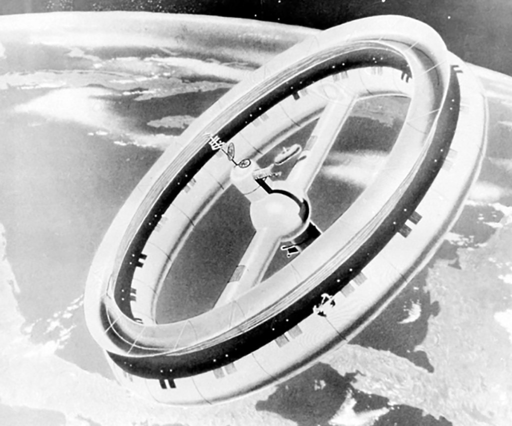
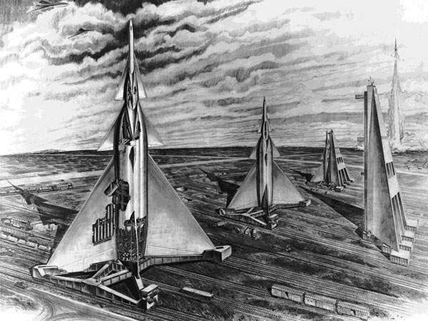
A series of articles published by Collier’s magazine beginning in March 1952 outlined Wernher von Braun’s plans for human spaceflight. The individual articles, edited by Cornelius Ryan, were authored by Willy Ley, Fred Lawrence Whipple, Dr. Joseph Kaplan, Dr. Heinz Haber, and Von Braun. The October issues detailed Von Braun’s plans to explore the Moon.
Werner von Braun’s lunar expedition would be a grand affair, reminiscent of the voyages undertaken during the Age of Discovery.
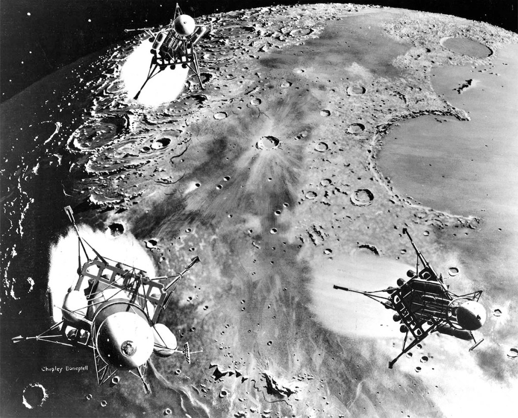
A 250-foot diameter space station would first be constructed in orbit by a fleet of ferry rockets. Once operational, the station would support the construction of three enormous lunar landers in earth orbit; each lander having the same mass as a Saturn V rocket.
For the voyage, two landers would carry crew and propellant for the return trip; the third is a one-way cargo vessel. Prior to the expedition, a manned orbiter would be sent to lunar orbit to photograph the surface and a suitable landing site would be selected.
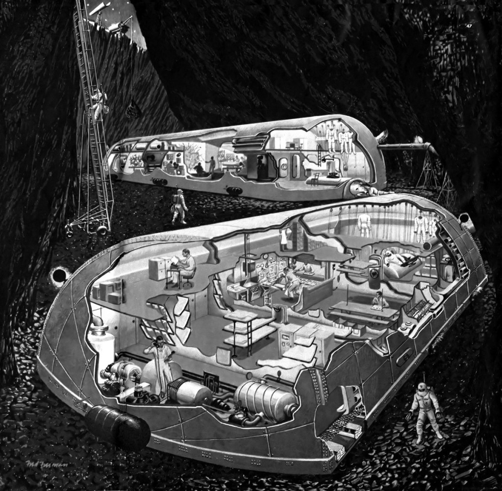
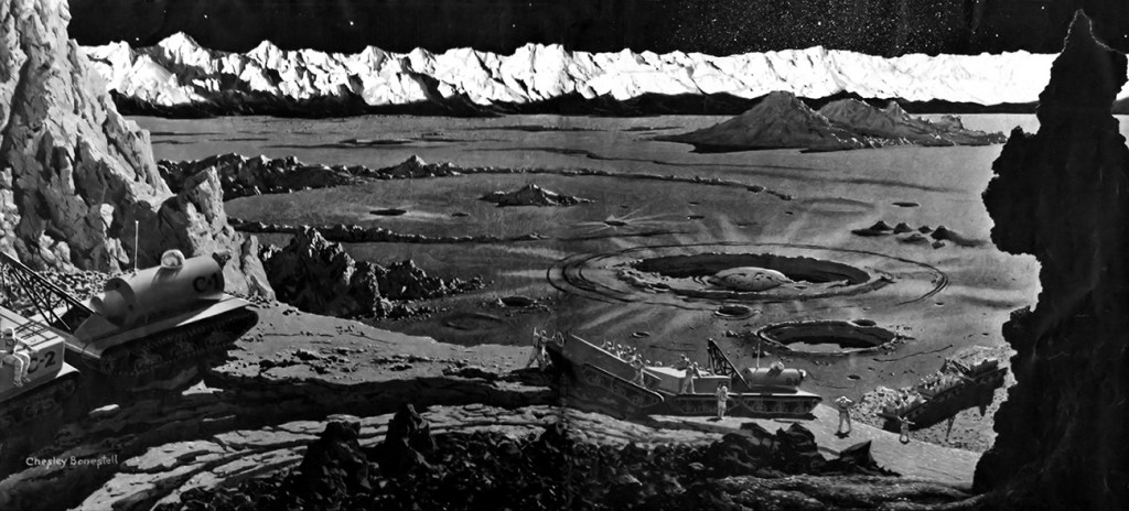
Final site selection would depend on the results of the photographic mission, but a site at Sinus Roris was considered the most suitable. Once on the lunar surface, the six-week stay begins with the crew setting up base camp. The cargo vessel is unloaded, and the hold is unbolted and lowered to the ground in sections to be used as underground crew accommodation. Three pressurized rovers provide transport.
With the addition of three trailers of supplies, two of the rovers would take a ten-man team on the trek to the crater Harpalus. Towards the end of the expedition the crew set up automatic telemetering stations, which will continue to radio data back to the earth, before returning to the earth orbiting space station.
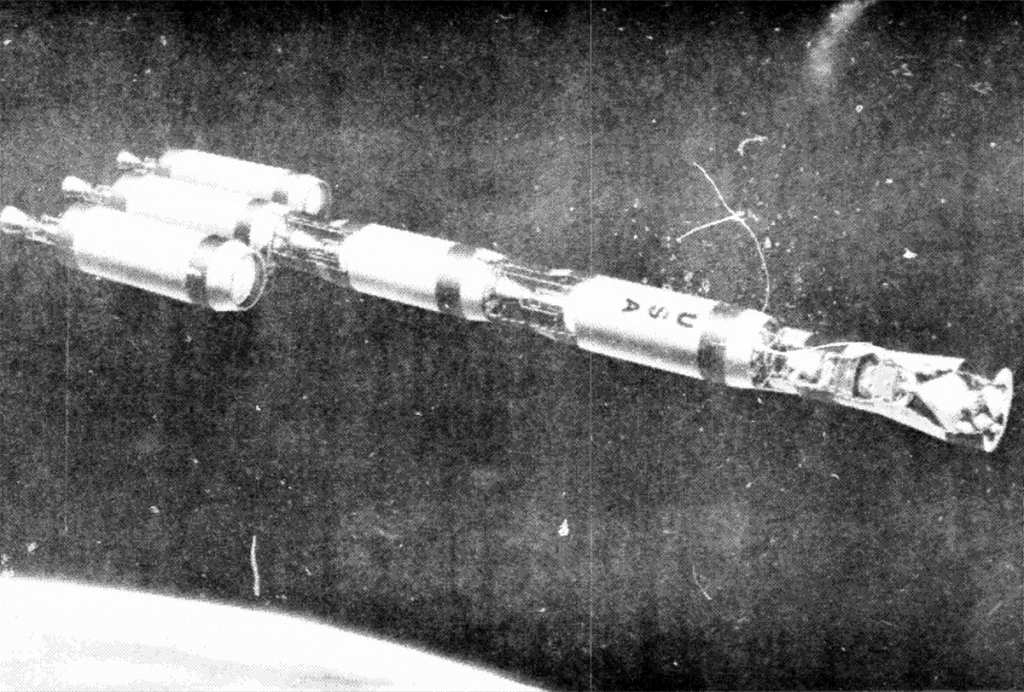
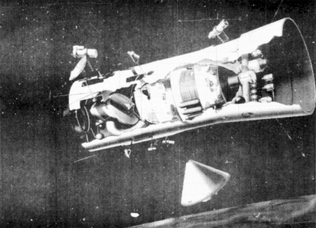
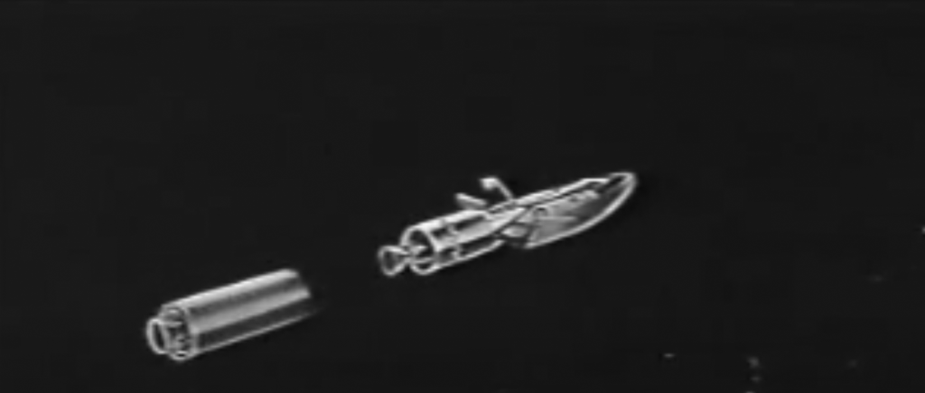
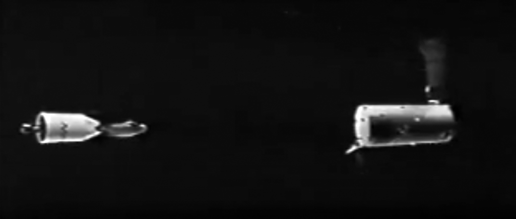
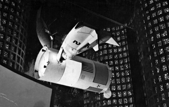
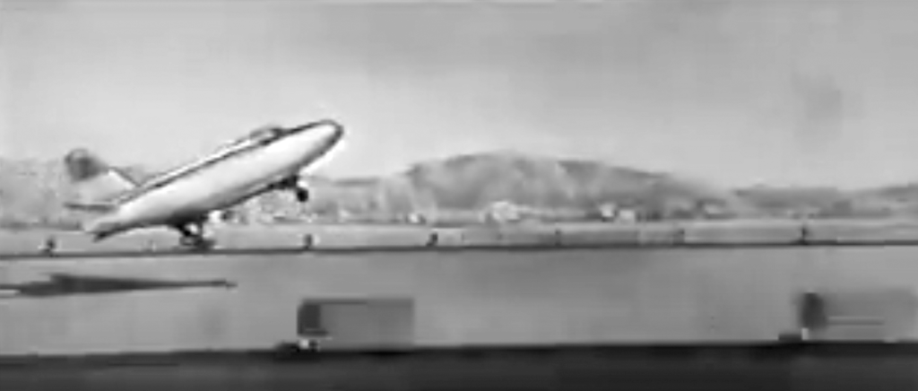
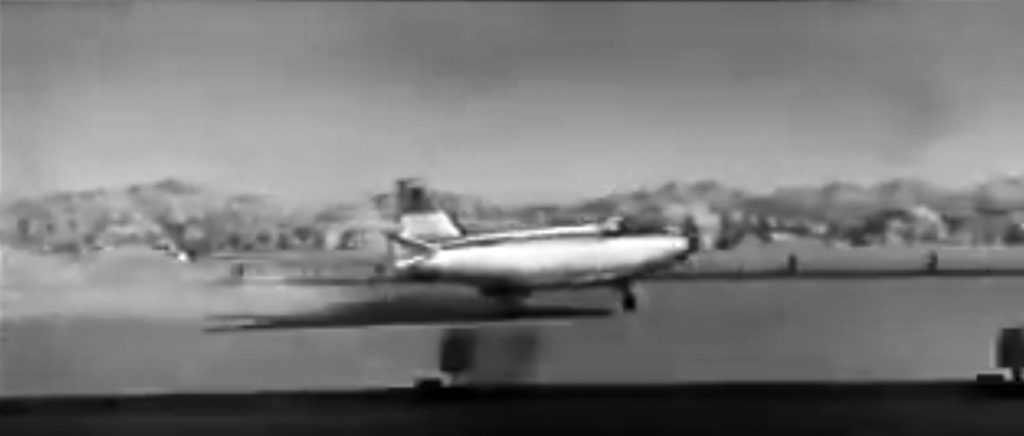
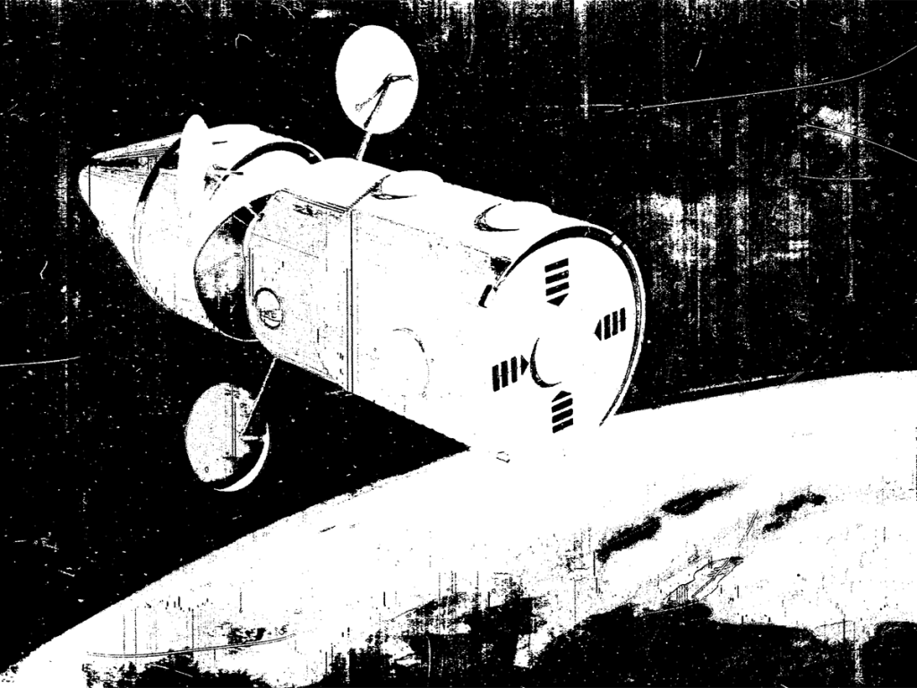
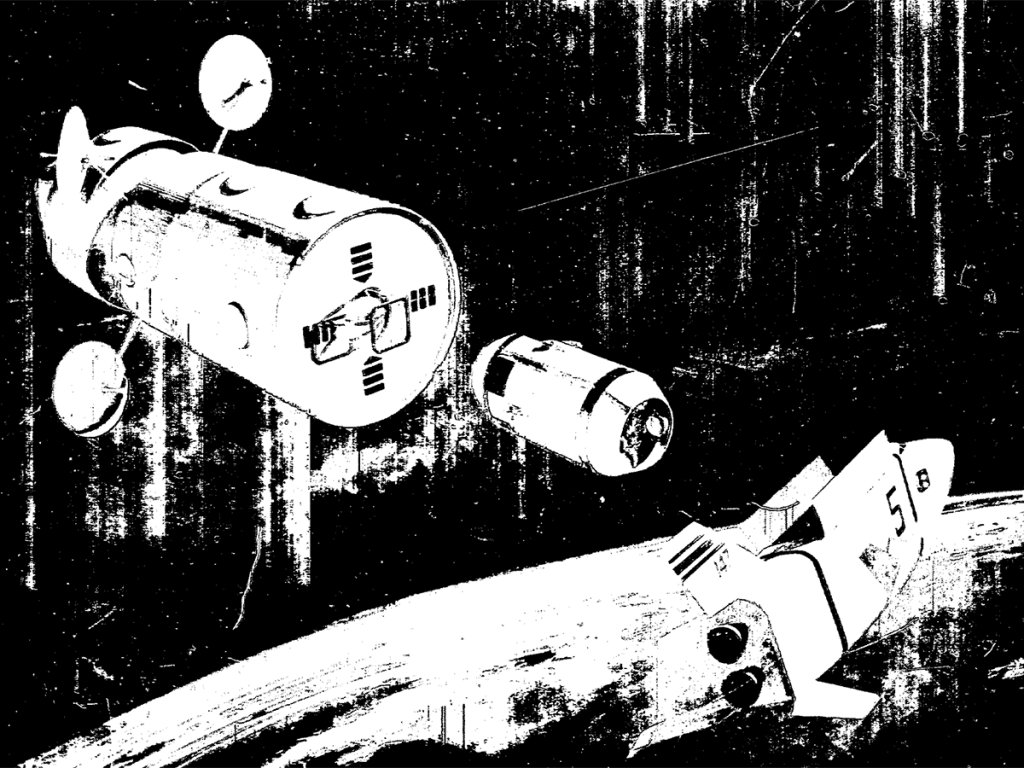
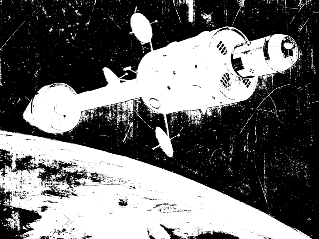
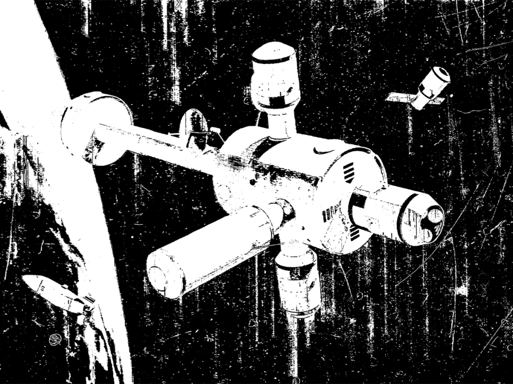
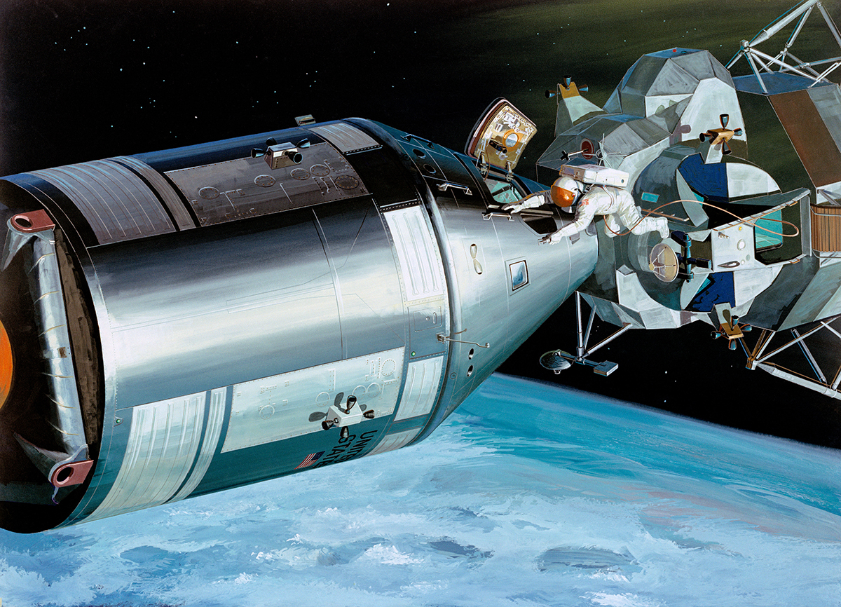
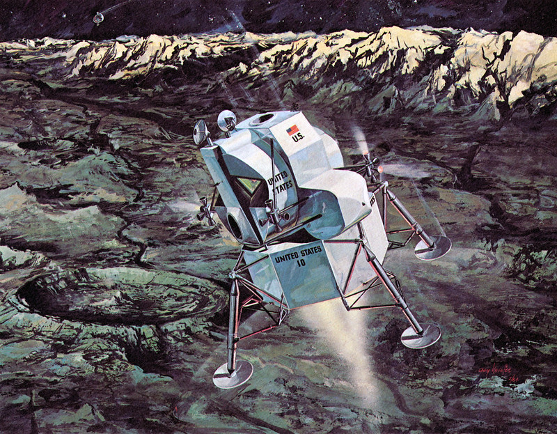
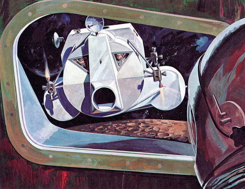
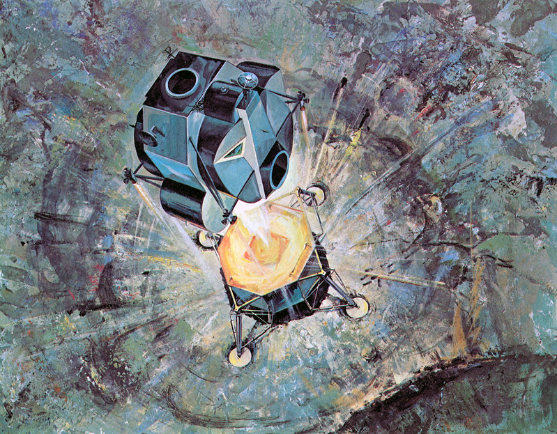
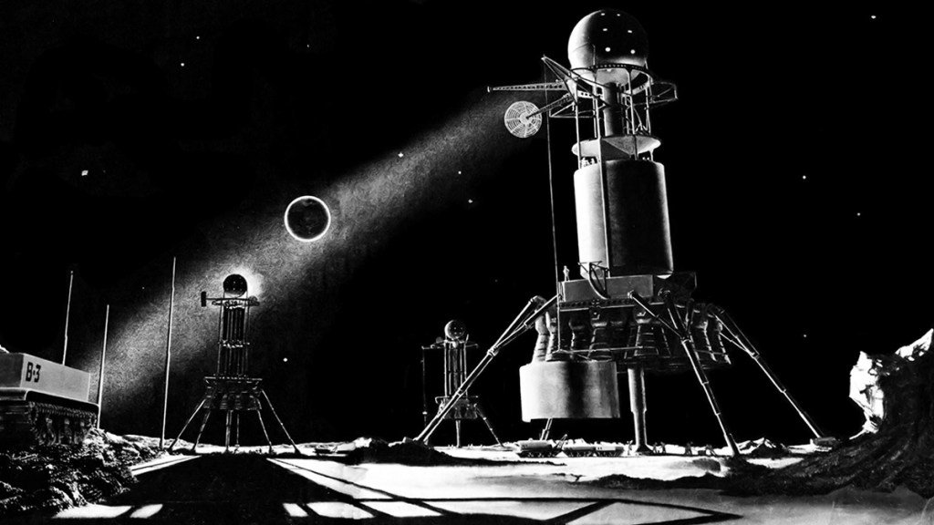
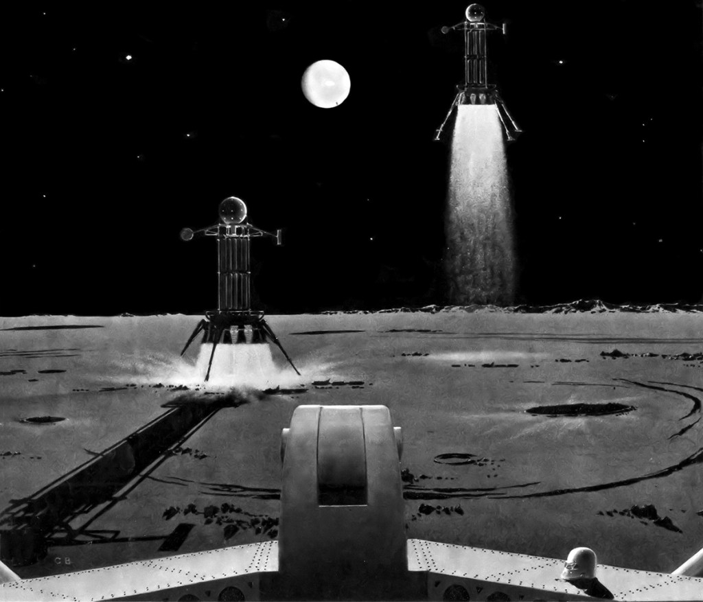
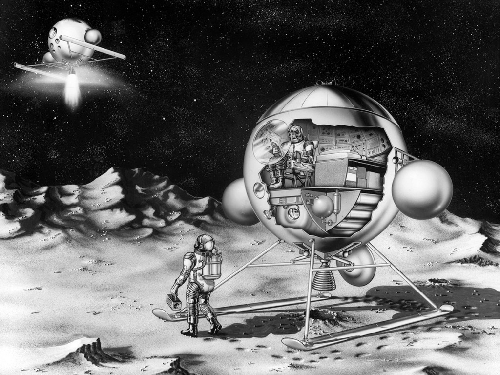
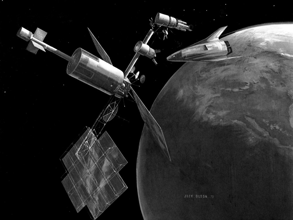
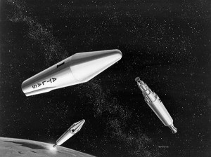
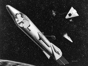
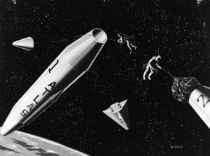
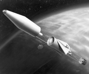
Disney employed von Braun as a technical consultant for an episode of Disneyland directed by Ward Kimball, one of Disney’s “Nine Old Men.” The live action portion depicts a reconnaissance mission to photograph the lunar surface. The hero ship, RM-1, would be built in orbit from modular components and discarded parts of the Man in Space vehicle. A dockable bottle-suit was provided for crew EVA.
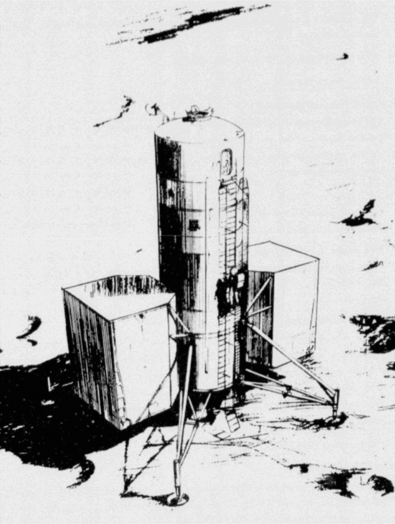
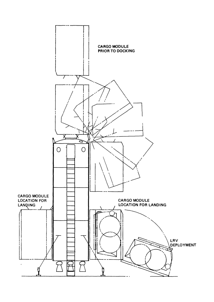
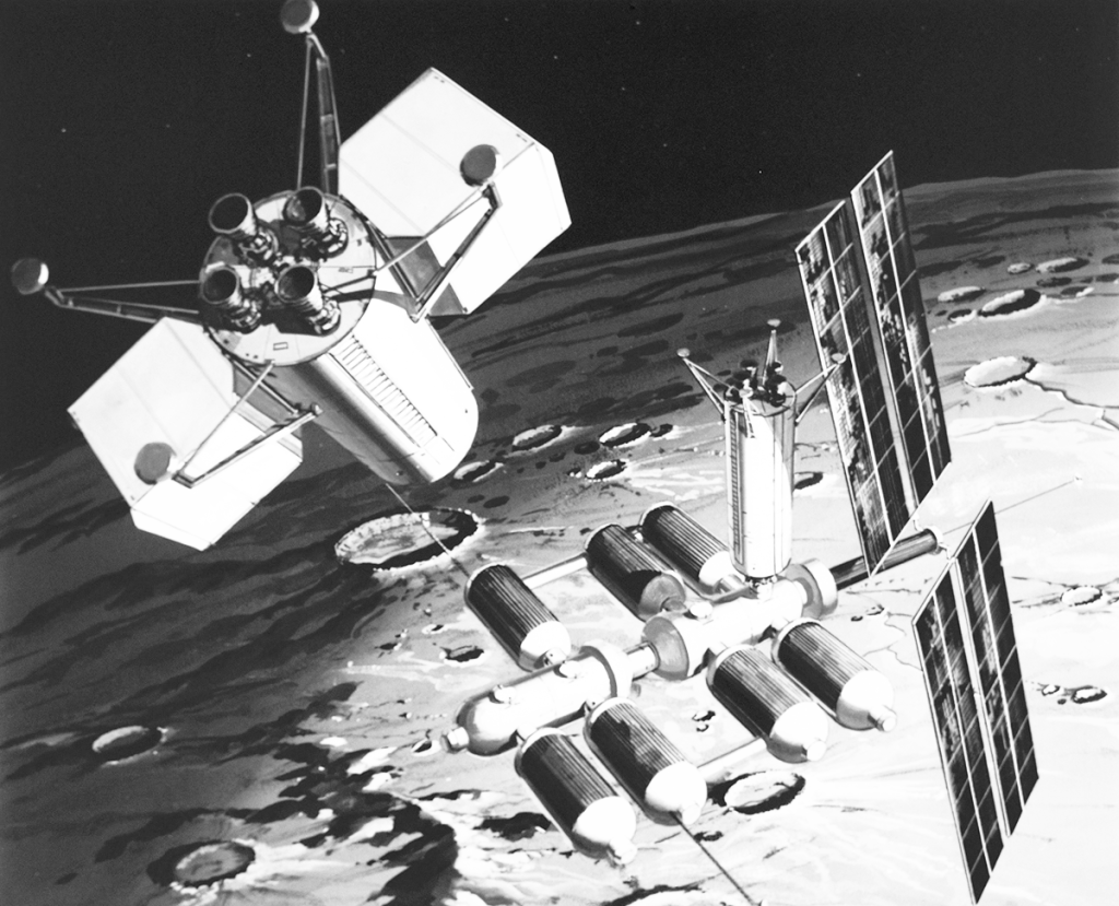
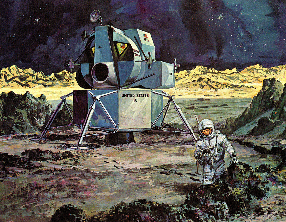
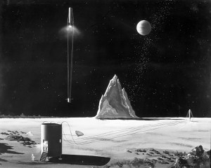
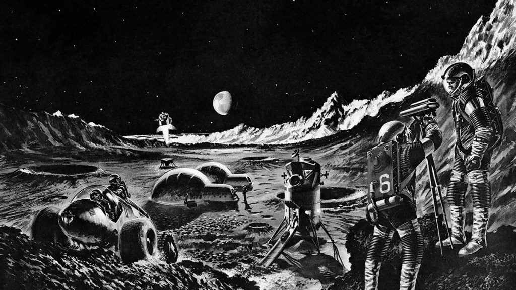
The Lunar Expedition was planned by the US Airforce as a manned mission to establish an underground base on the moon by 1968; essential to demonstrate US technological dominance. The lander – consisting of a manned re-entry vehicle, a lunar landing stage, and a lunar launch stage – would be launched from earth by a three-stage liquid or solid propellant booster to escape velocity on a lunar intercept trajectory. A cargo module without the capability for lunar launch would also be built.
Not to be outdone by the Airforce, the US Army convened a taskforce in March 1959 with the goal of establishing a lunar outpost by the quickest practical means. Under the direction of Maj. Gen. John B. Medaris of the Army Ordnance Missile Command, and in collaboration of Von Braun’s team, the task force completed a report in June that proposed a manned moon landing in 1965, followed by the construction of an operational lunar outpost in 1966. Construction of the final base would require 61 Saturn I and 88 Saturn II launches, transporting 490,000 pounds of cargo and equipment to the moon.
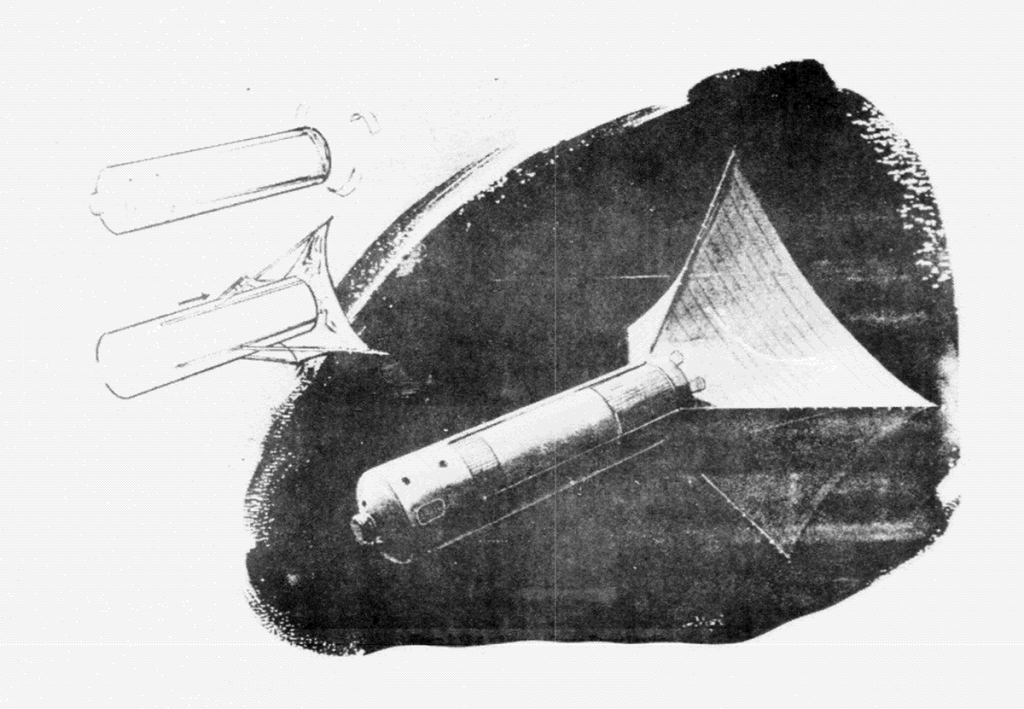
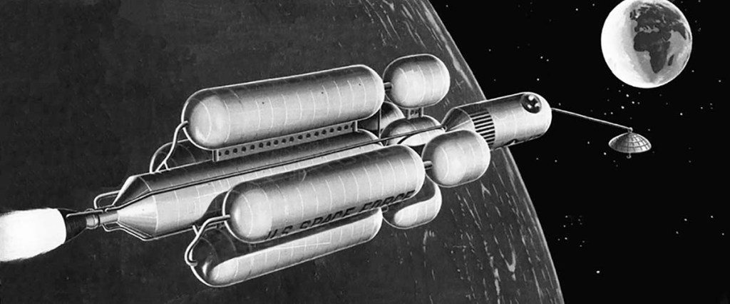
The Heteropowered Earth-Launched Inter-Orbital Spacecraft (HELIOS) was a two-stage interorbital launch vehicle proposed by Krafft Ehricke to deliver crewed modules to the moon. A recoverable booster stage would carry a nuclear second stage to orbit. The second stage would separate from its payload and, relying on distance rather than heavy shielding, tow the crew gondola under nuclear power to a soft landing on the lunar surface.
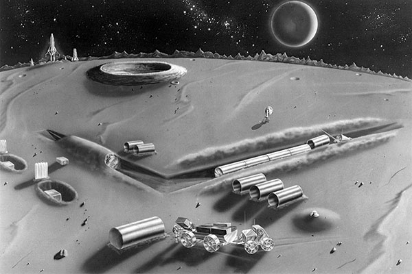
Republic Aviation design for a lunar facility painted in 1961
Lockheed ELO – 1961-1963
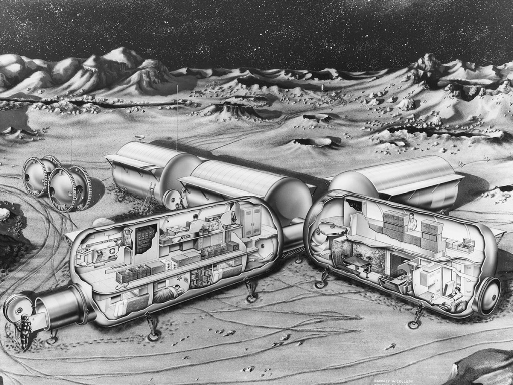
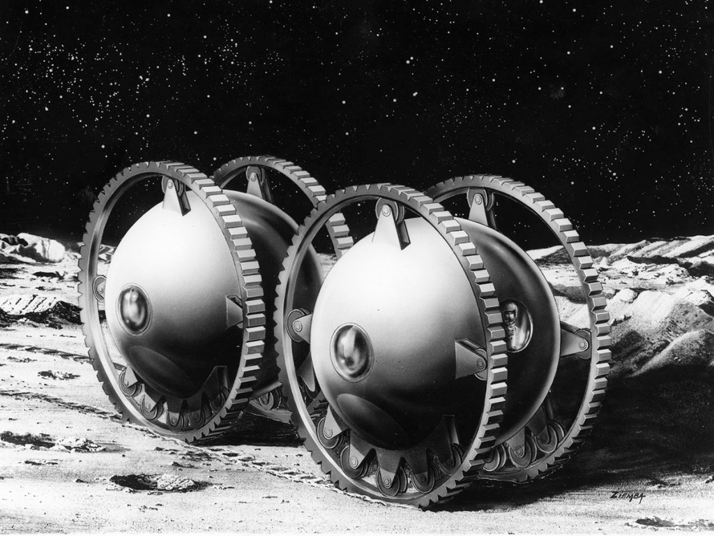
Within a month of John F. Kennedy’s address on May 25, 1961, committing the United States to landing a man on the Moon, Lockheed initiated a series of internally funded feasibility studies to position the company favorably in the expected competition for NASA contracts. The core of these lunar projects was a series of engineering studies that focused on short duration and permanent manned Moon missions. The permanent base was designed to support 100 astronauts in cylindrical modules. The base would be re-supplied by a Saturn C-5 every 30 days.
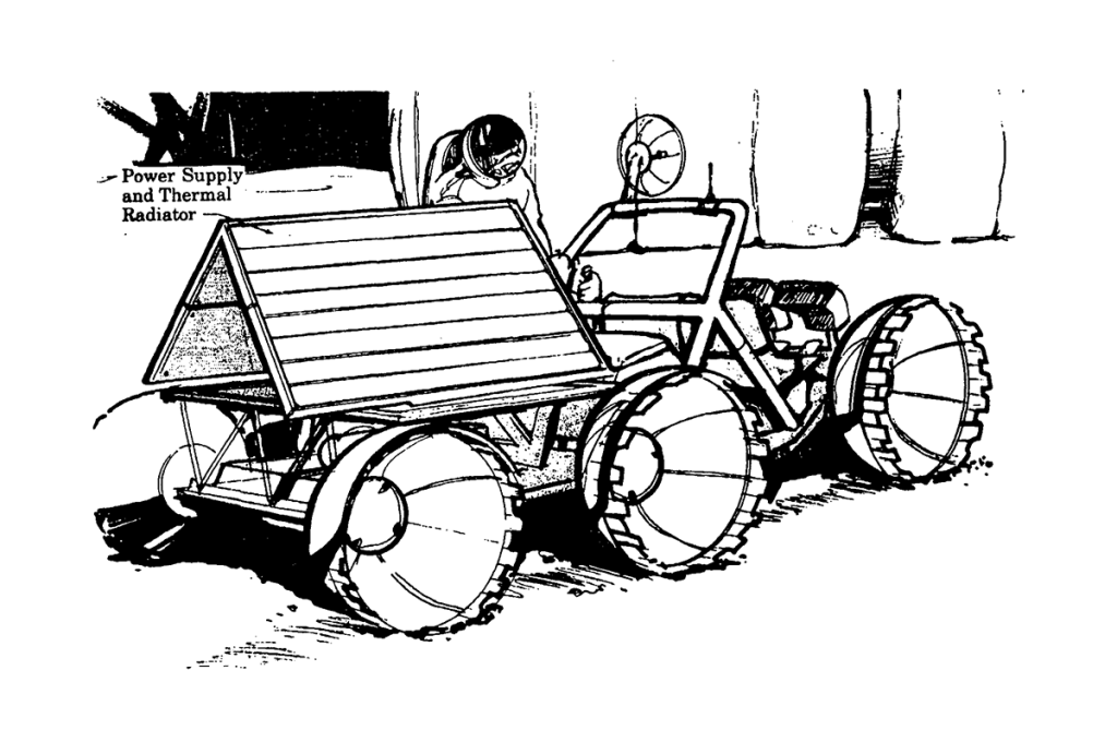
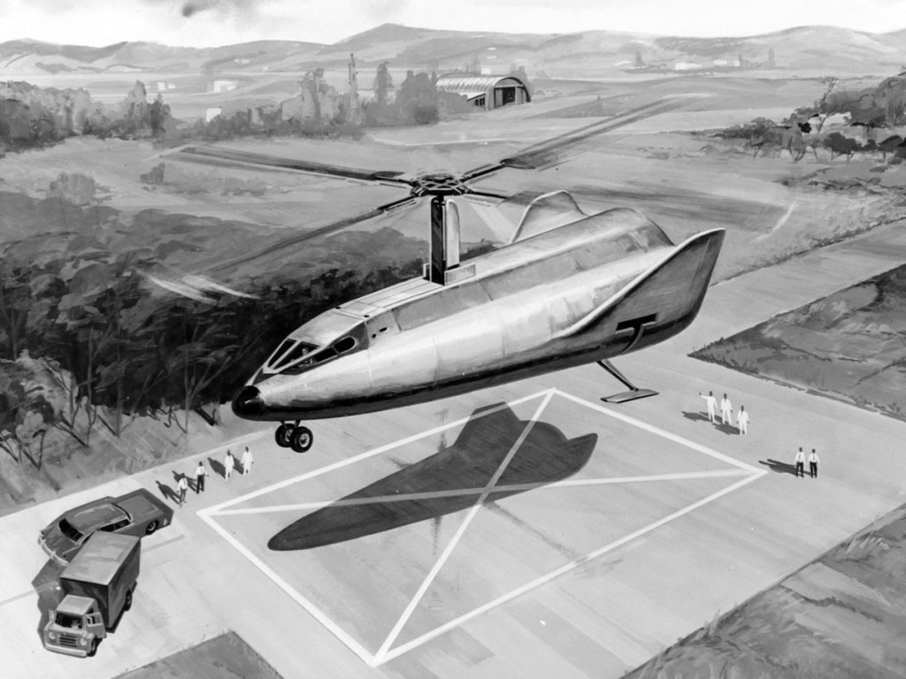
A spherical, 2-man, lunar tractor would be used for construction and surface transportation. A long-distance flying vehicle would be available for long-distance missions. Power for the base would be provided by a SNAP reactor.
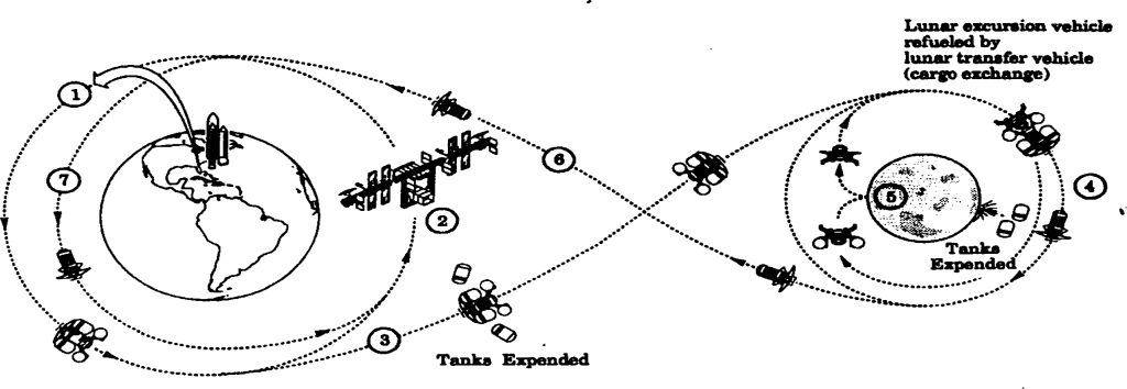
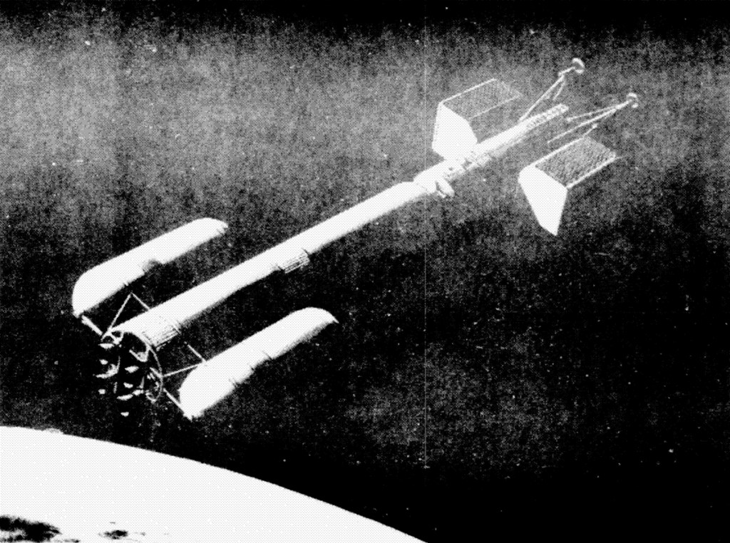
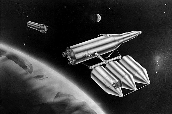
In 1964 Philp Bono proposed using the enormous Reusable Orbital Module-Booster & Utility Shuttle (ROMBUS) he was developing at Douglas for a manned lunar mission. The lander ROMBUS would rendezvous in low earth orbit with two tankers and refuel. After a soft landing on the moon, the empty fuel tanks would be used to construct a temporary lunar habitat. The long-term goal of Selena was to establish a 1000-man lunar colony to support the follow-on Deimos Mars expedition.
The Apollo Applications Program was created by NASA Headquarters to develop science-based human spaceflight missions using Apollo hardware. NASA estimated it would require $450 million in 1967 to fully fund the AAP, with over $1 billion being required in 1968. The Johnson Administration declined to fund it adequately, allocating $80 to the program in Fiscal Year 1967.
AAP Programs
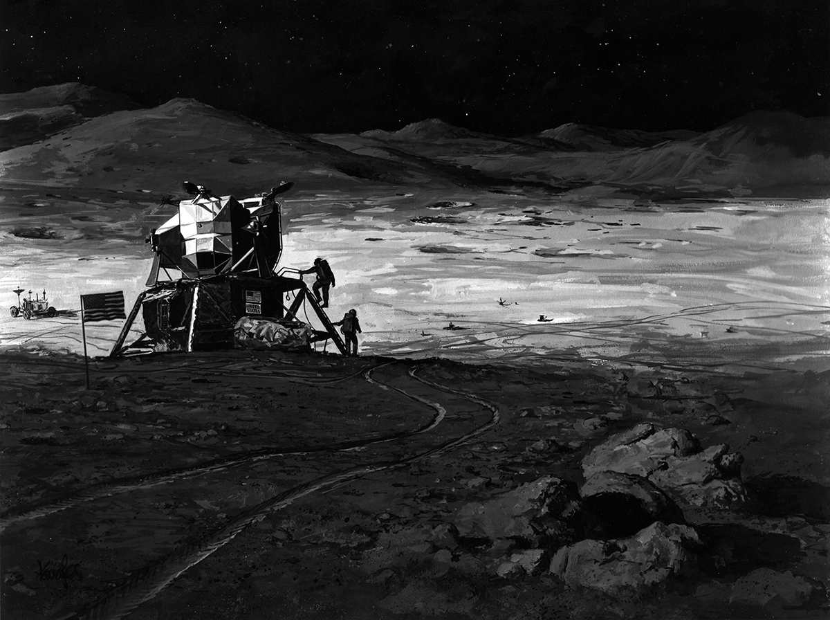
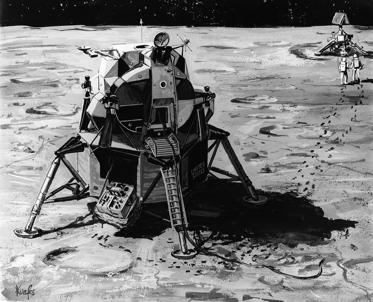
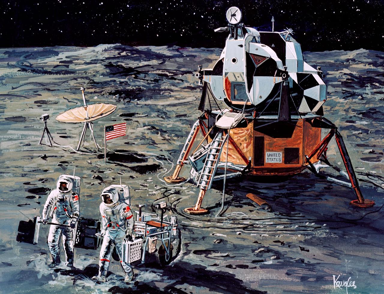
AES (Apollo Extension Series) Lunar Base
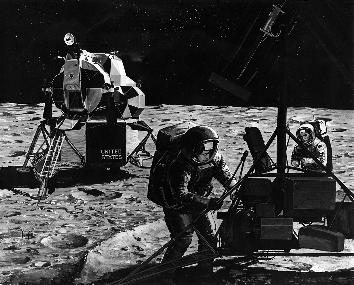
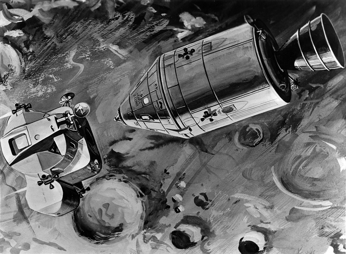
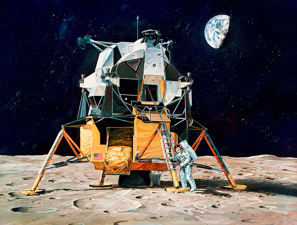
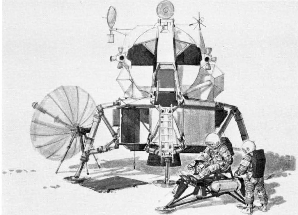
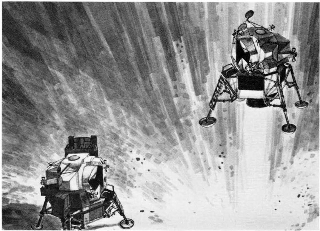
Beginning in 1972, NASA would begin a series of lunar exploration missions using a version of the Apollo LM modified for extended stays of 3 to 4 days. A 28-day lunar survey mission would be flown in 1974. Beginning in 1975, dual-launch crewed missions would begin: A Saturn V launch would deliver a manned Apollo CSM and LM Shelter to lunar orbit. The CSM would transpose and dock with the LM Shelter. Once braked in lunar orbit, the un-crewed LM Shelter would separate and land autonomously. A second Saturn V launch three months later, using an Extended CSM and a LM Taxi, would transport a crew to the LM Shelter for surface visits of up to a fortnight.
Vehicle Development
Extended CSM. A CSM would be refitted to provide enough consumables to operate with one astronaut for up to 30 days in lunar orbit.
LM Shelter, an Apollo LM with three-month quiescent (inactive) capability. The ascent stage engines and associated tankage would be removed and replaced by consumables and equipment to accommodate two astronauts for up to 14 days.
Apollo LM Taxi, an Apollo LM would be modified to give it a 14-day quiescent lunar stay time, with 3 days of operational use. The Taxi would be shut down after landing, and reactivated two weeks later when the crew would return to the CSM.
Lunar mobility vehicles that could be accommodated in the payload bay of the LM Shelter would be developed.
ALSS (Apollo Logistics Support System)
Developing the LM into a dedicated cargo truck would allow delivery of loads up to 11,000 lbs to the lunar surface, this would mean larger surface shelters and pressurized vehicles could be landed enabling stays of up to 30 days.
Vehicle Development
LM Truck, a Lunar Module descent stage adapted for unmanned delivery of payloads to the lunar surface.
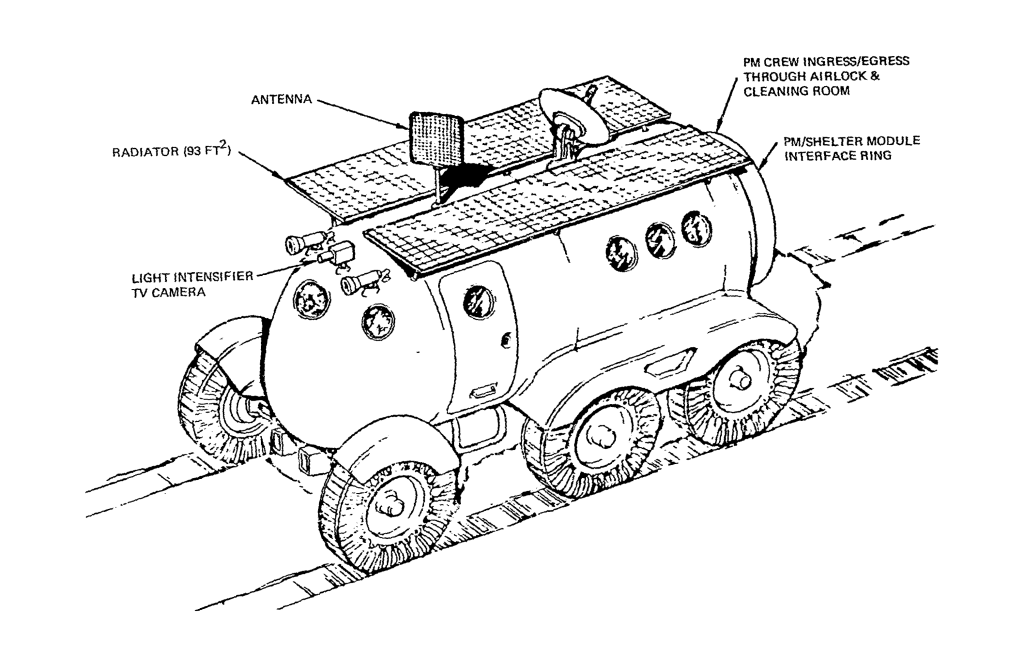
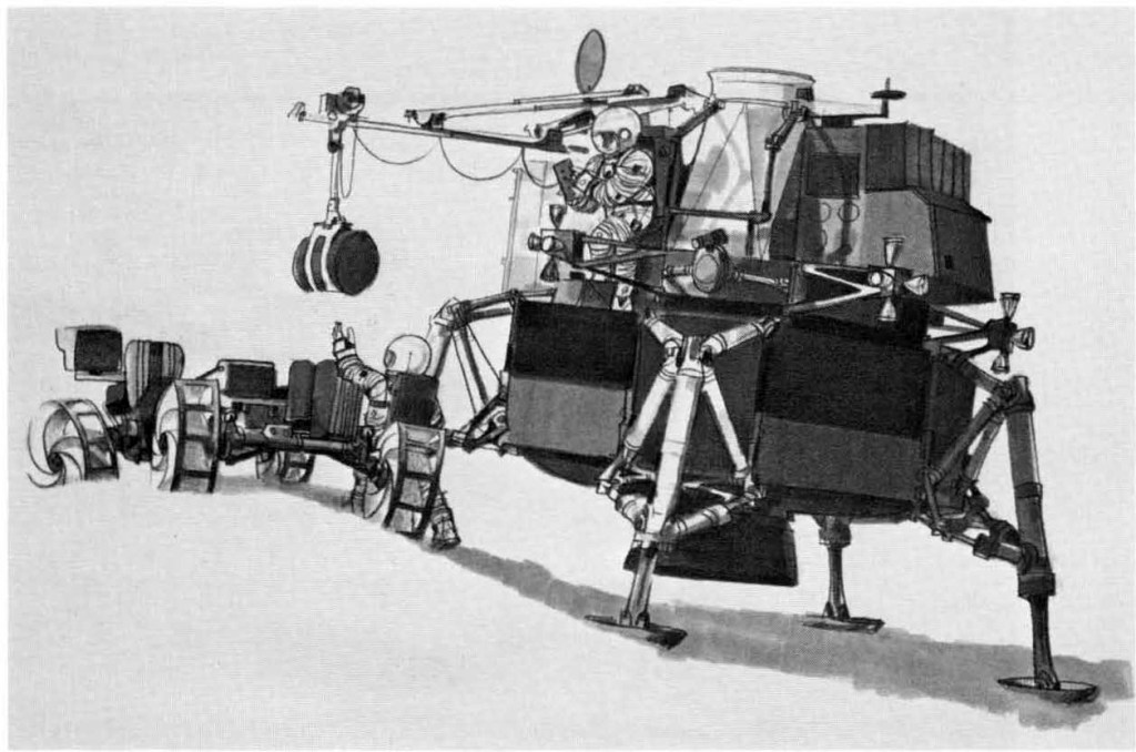
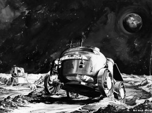
MOLAB, a pressurized rover, would provide the crew with mobility and shelter during long-range lunar traverses.
A Lunar Flying Vehicle (LFV) would give the crew the means of returning to the LM Taxi should the MOLAB vehicle became disabled.
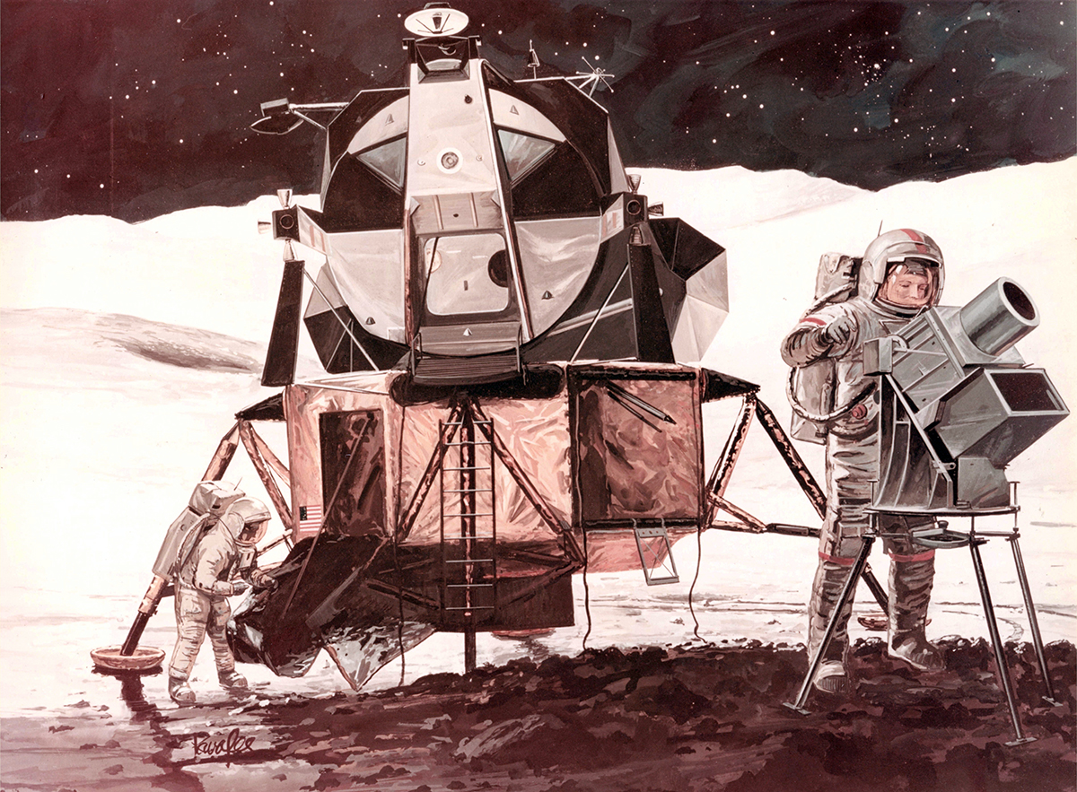
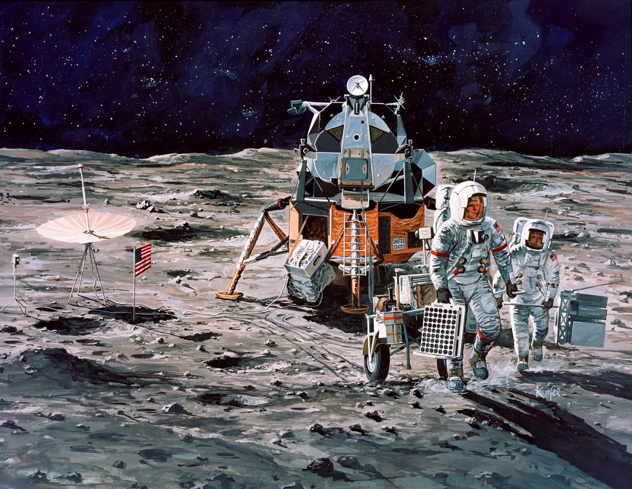
LESA (Lunar Exploration System for Apollo)
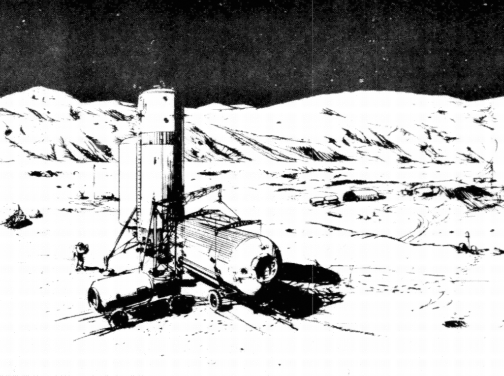
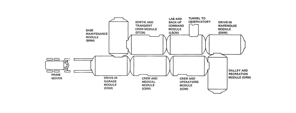
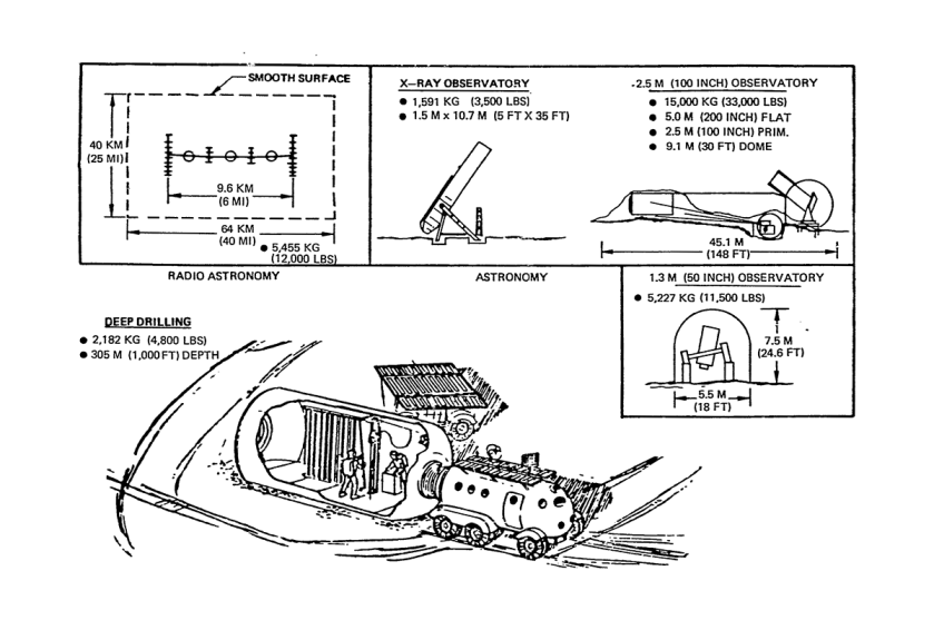
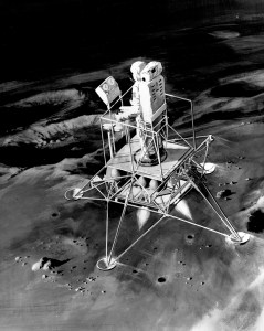
In the final evolution of the AAP, a new lunar lander would be developed taking full advantage of Saturn V’s trans-lunar payload capability. With a payload capacity of nearly 28,000 lbs., the new LLV would be capable of carrying life support systems, consumables, shelter, and a Lunar Roving Vehicle to the moon on a single launch. The new vehicle would give astronauts a 90-day exploration window. Once the LESA landed, a crew of three astronauts would arrive to make it operational and deploy the LRV. Traverses as far 400 km could be undertaken from the base. Later models would allow for an 18-man installation to be built, manned over 24 months by a revolving crew.
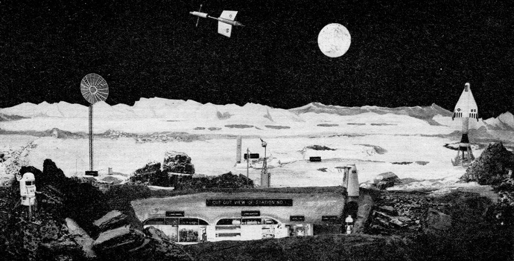
In the late fifties the Boeing Aircraft Company conducted an exhaustive study that culminated in what they called the Program for Astronomical Research and Scientific Experiments Concerning Space. In essence, PARSESCS was a roadmap to a future in space that begins with manned spaceflight in earth orbit and ends with human exploration of other worlds. Boeing released a number of reports relating to PARSECS, notably one that accompanied a talk given by (then) SVP Wellwood E. Beall at the Commodore Hotel in New York in April, 1960 for the Society of Automotive Engineers. In the accompanying paper, Beall says: “The program has the general objective of providing a focus for Boeing personnel engaged in space-oriented research not directly associated with military programs. Specifically it tabulates requirements for space research drawn from many sources and then defines the vehicles and systems to accomplish the resultant broad scope of objectives.”
If you’re yearning for more information, I’ll suggest this thread on Secret Projects Forum. The technical paper that accompanied Beall’s SAE presentation can be downloaded here.
PARSECS MISSIONS
Mission I – Earth Satellite Observatory
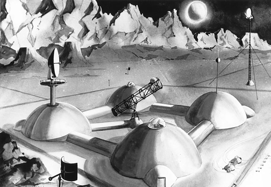
Mission II – Moon Colony
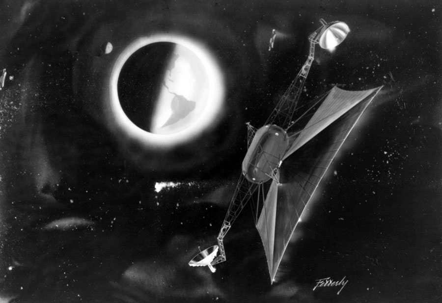
Mission III – Counter Moon
Mission IV – Interplanetary Probes
Mission V – Close Solar Orbit
Mission VI – Trojan-Point Observatories
Mission VII – Out-Of-Ecliptic-Orbit
Mission VIII – Planetary Exploration
Image credit: Boeing Aircraft Company Images: Mike Acs, SDASM Archives
In December 1968, NASA convened the Space Shuttle Task Group which set out the basic missions and characteristics of a reusable launch system, borrowing the term ILRV from the Air Force studies. Development would take place in four phases; Phase A: Advanced Studies; Phase B: Project Definition; Phase C: Vehicle Design; and Phase D: Production and Operations.
Each of the agencies involved favored different configurations for the shuttle: The FDL and Draper Laboratories favored a swept delta wing spaceplane, like the Dyna-Soar, for maximum cross range on re-entry. NASA Langley and Edwards AFB favored a lifting body, based on the HL-10 then under test which had a weight advantage but lower cross range.
A Request for Proposal was issued jointly by NASA Houston and NASA Huntsville in January 1969, for an eight-month Phase A study. General Dynamics, Lockheed, McDonnell Douglas, Martin Marietta, and North American Rockwell won ILRV study contracts. The ILRV was to be capable of delivering propellent, propulsive stages and payloads to orbit, orbital launch and retrieval of satellites, satellite maintenance, space station logistical support and short duration crewed missions. The report considered three classes of vehicles: reusable orbiters launched on expendable boosters, stage and a half vehicles and two-stage vehicles where both the booster and orbiter were fully reusable. Martin Marietta’s design was ultimately dropped, but they continued to develop their vehicle using company funds.
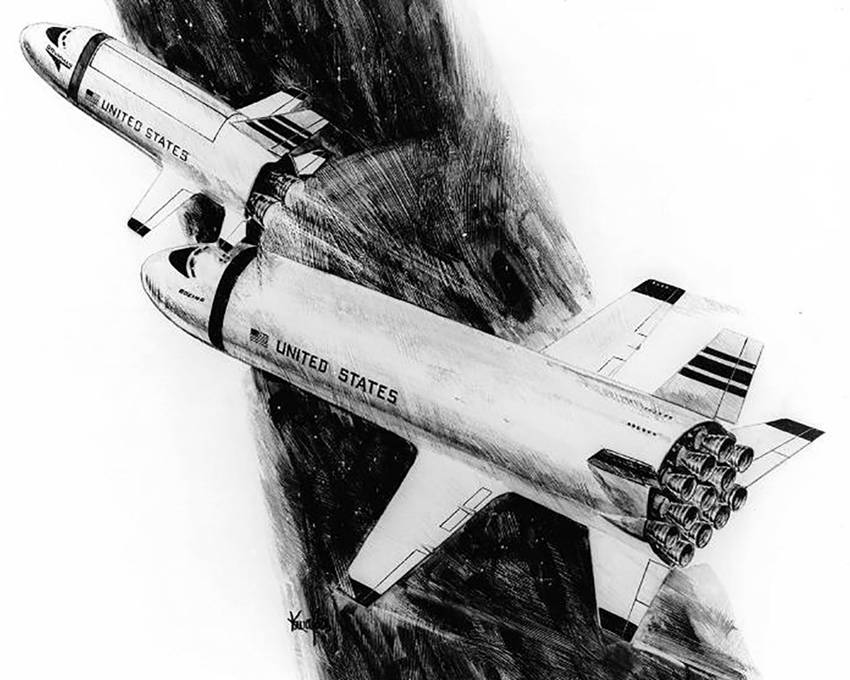
General Dynamics
After further study, General Dynamics abandoned the Triamese design in September as it had proven difficult to make one aerodynamic shape serve both as a booster and orbiter. After a contract extension, the company settled on a more traditional two-stage v-tailed design.
Lockheed
Lockheed’s Phase A contract concentrated on fully reusable versions of the STAR Clipper. Their final design was a delta-planform lifting-body orbiter paired with a body-wing booster.
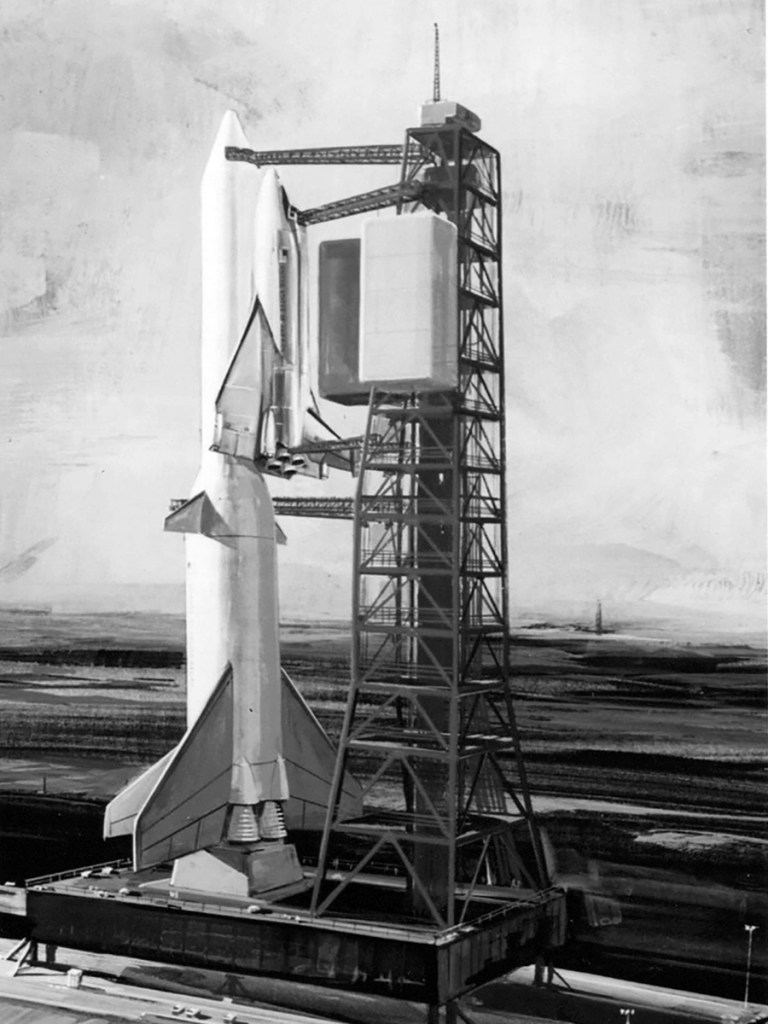
Martin Marietta
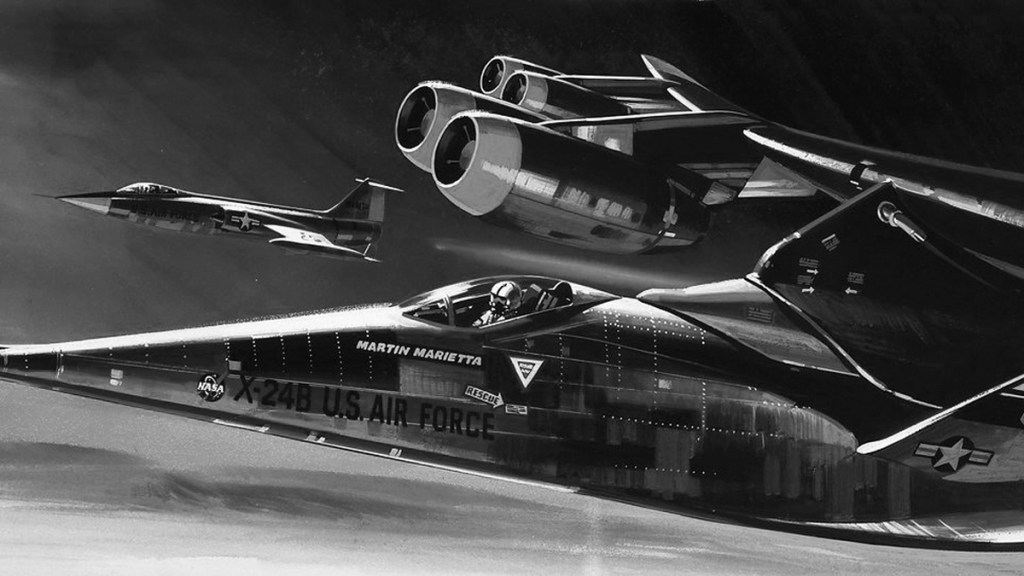
Martin Marietta developed the Spacemaster, an orbiter based on the X-24B with an unusual catamaran style booster.
McDonnell Douglas
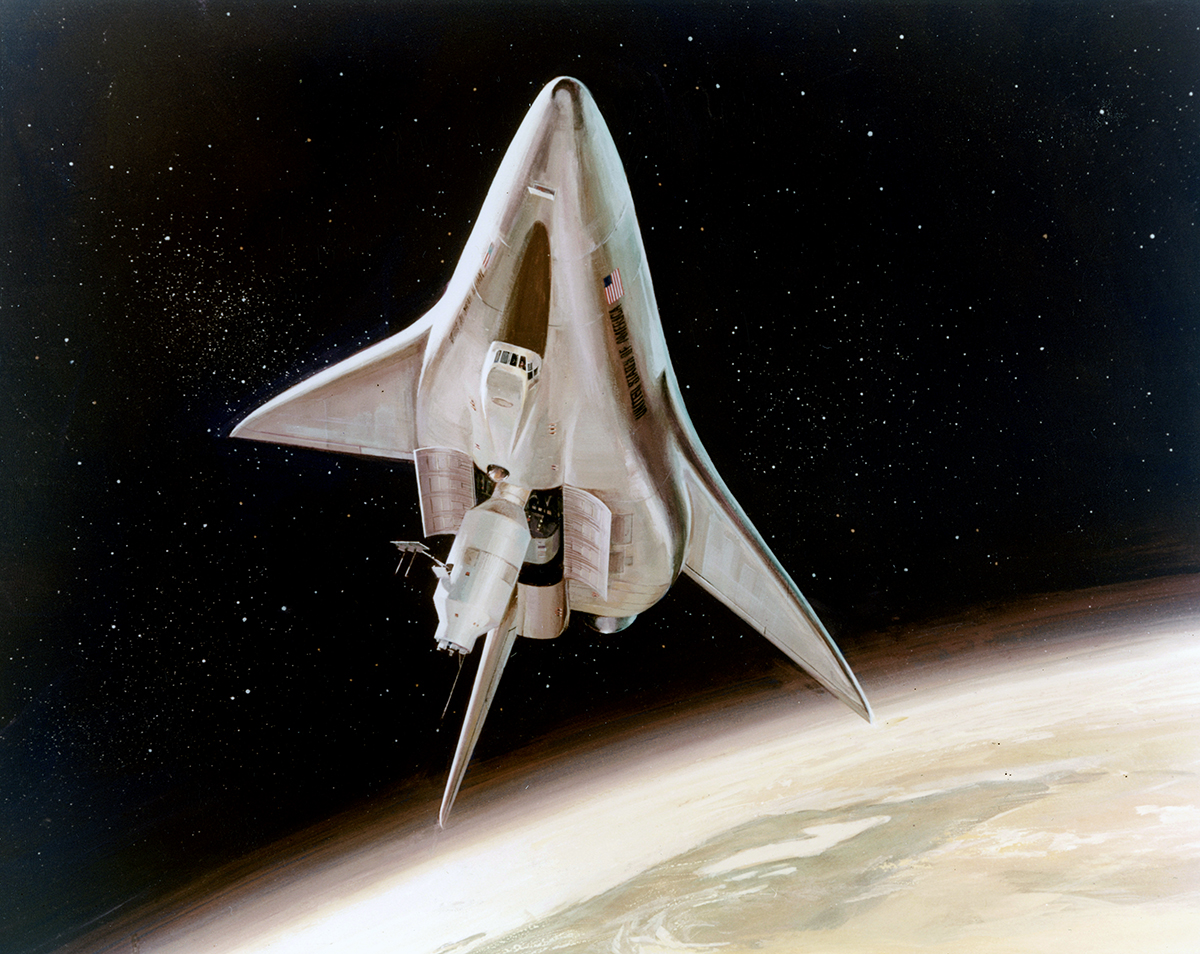
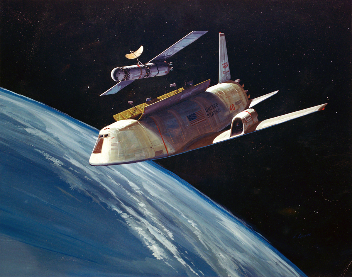
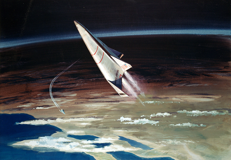
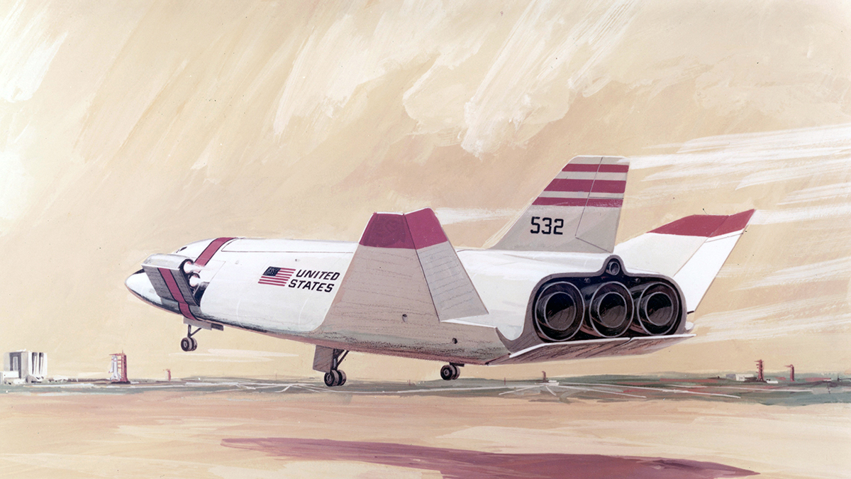
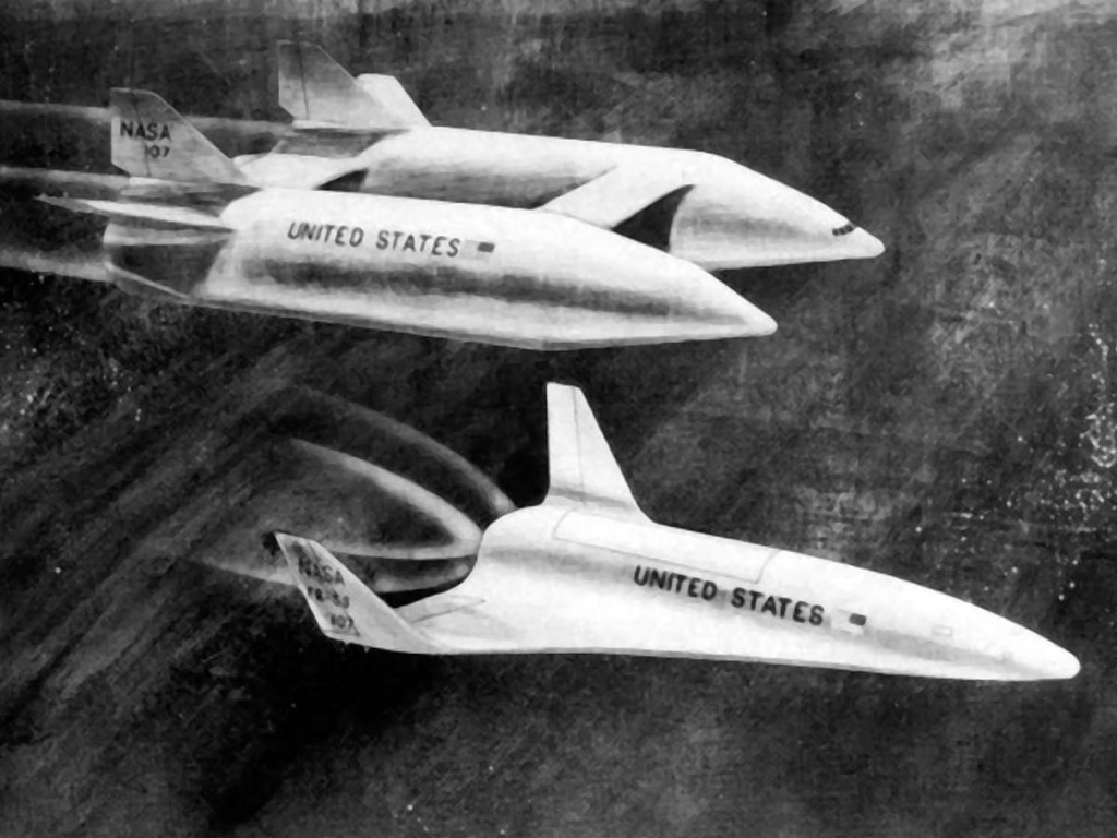
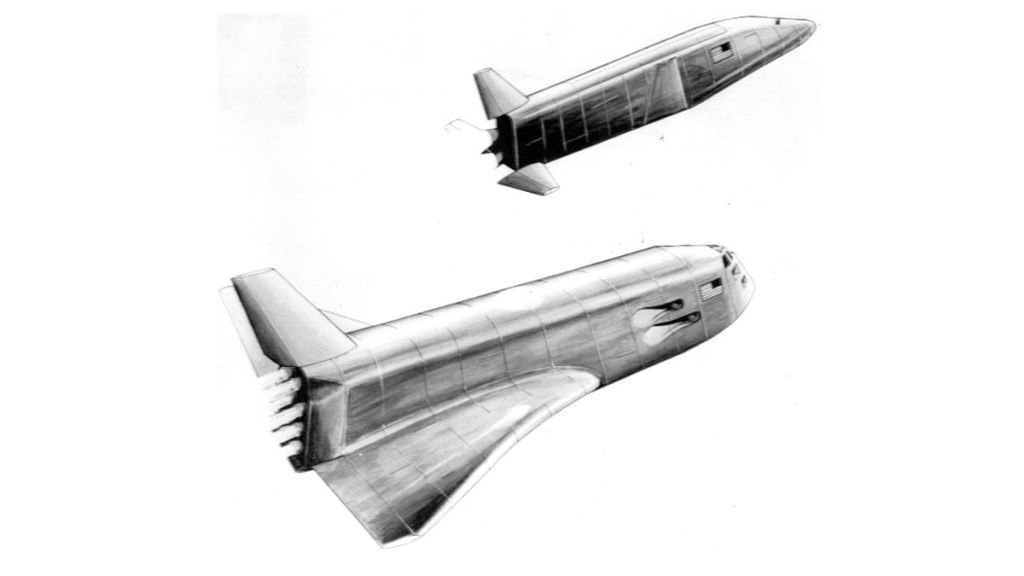
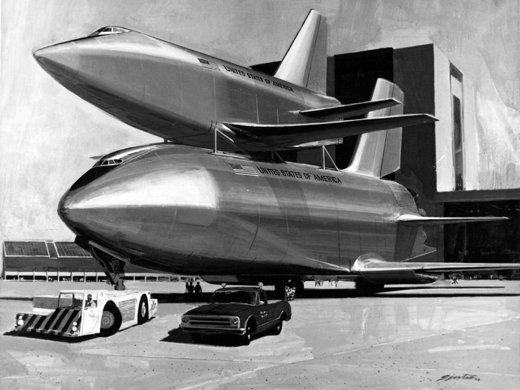
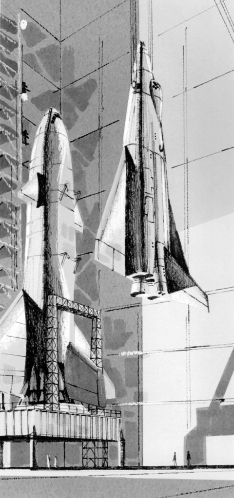
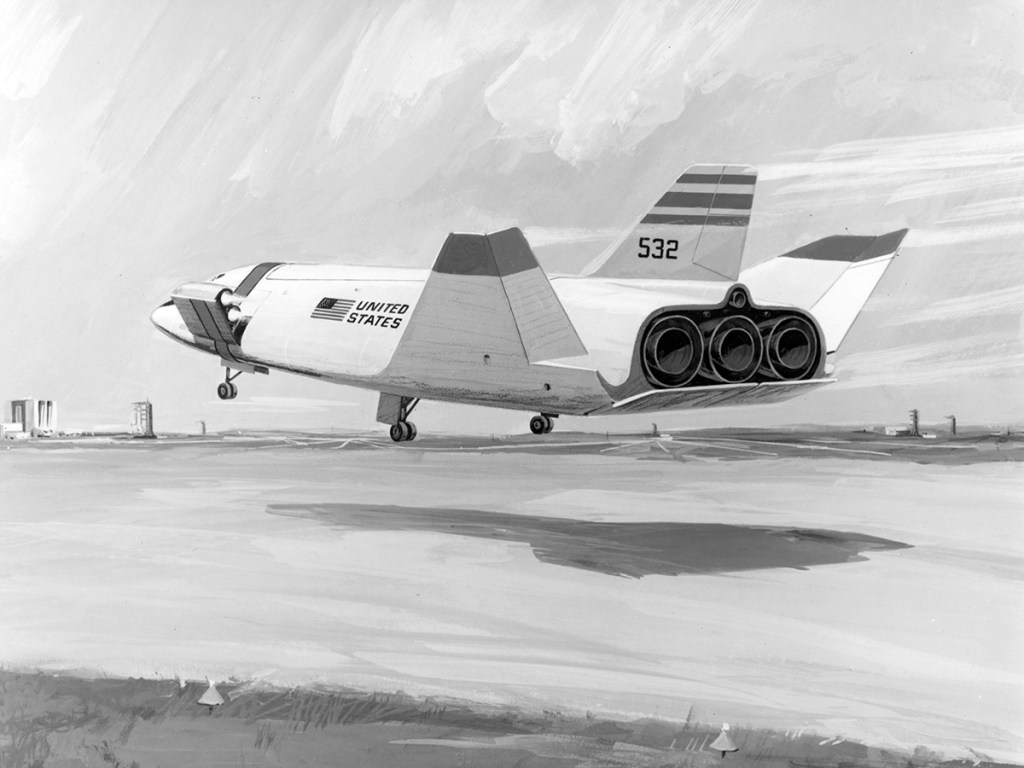
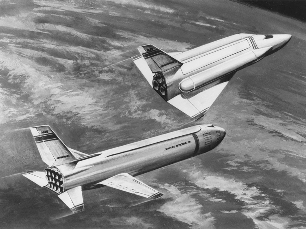
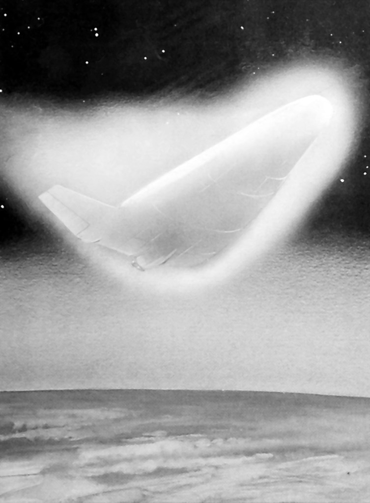
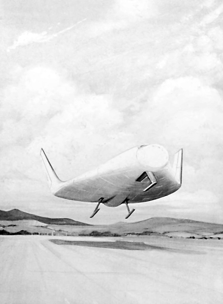
McDonnell Douglas studied partially reusable designs early in Phase A, receiving additional funding in July 1969 to investigate Langley’s HL-10 Lifting Body. The company additionally proposed a number low cost designs. The “drawbridge” orbiter would re-enter with folded wings for high cross-range military missions, and unfolded wings for low cross-range missions when the heat loads would be lighter. A smaller alternative design was derived from their 1968 ILRV proposal.
North American Rockwell
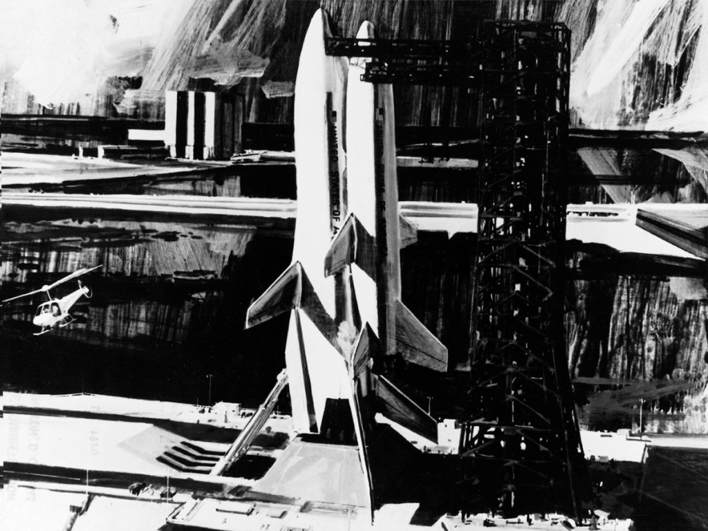
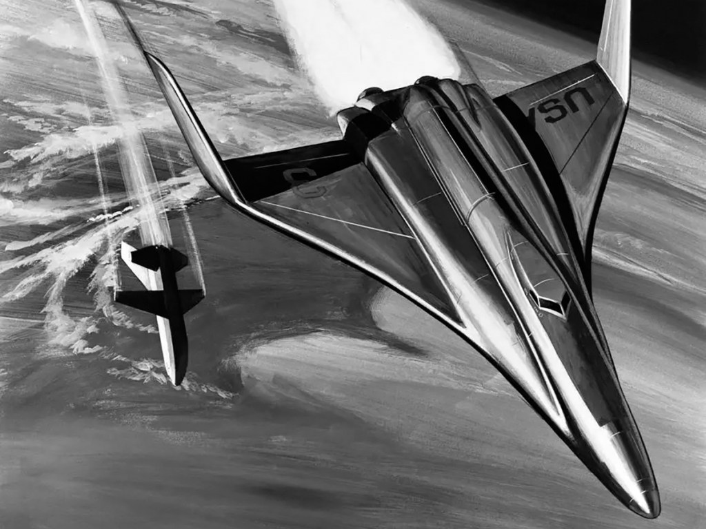
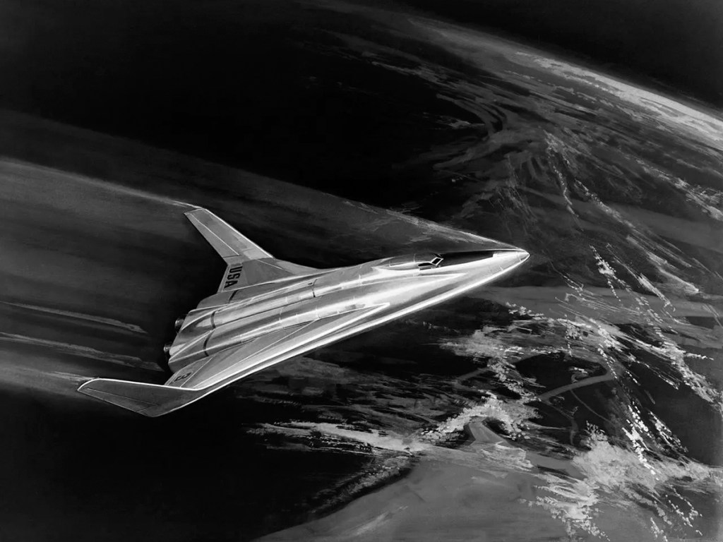
Initially focused on partially reusable designs, in June North American received additional funding from NASA to investigate a concept by the Manned Space Center’s Maxime Faget. Faget disliked the lifting-body designs for their poor low speed handling and believed they would be difficult to develop. Faget’s more conventional design was flat-bottomed with low-mounted swept wings. The vehicle would re-enter the atmosphere in a nose high attitude, presenting its lower surfaces to the airflow to blunt its descent. As the vehicle reached the lower atmosphere, it would pitch forward to a conventional flying attitude with jet engines powering the vehicle to a landing. He called his design the DC-3. In July, North American received additional funding to develop modular space station and space base concepts.
October 1969 – USAF Involvement
The cancellation of the X-20 in December 1963, and MOL in June 1969 left the Air Force without a manned space program of its own and demonstrated a need to cooperate with NASA in order to place military astronauts in orbit. NASA in turn sought Air Force support. In October NASA and the Air Force agreed to develop a reusable space vehicle that would meet both civilian and military requirements, and in so doing create a national system.
As development progressed, Air Force involvement began to shape design. The Airforce high cross-range requirement necessitated a large delta wing, which effectively eliminated the DC-3 and FR-3A from consideration.
January 1970 – Clearing House
A meeting was held in Houston to study all the in-house concepts. Over the next year, several designs were dropped including the entire series of lifting-body derived vehicles.
July 1970 – Phase B
NASA now stipulated a fully reusable system with both component vehicles being able to undertake ferry flights between landing and launch sites, ending any consideration of a partially expendable system. Funding was awarded to consortiums led by North American Rockwell, and McDonnell Douglas. In addition, both teams were instructed to study alternate orbiters: the straight-wing low cross-range Faget design and delta wing configurations for high cross-range missions.
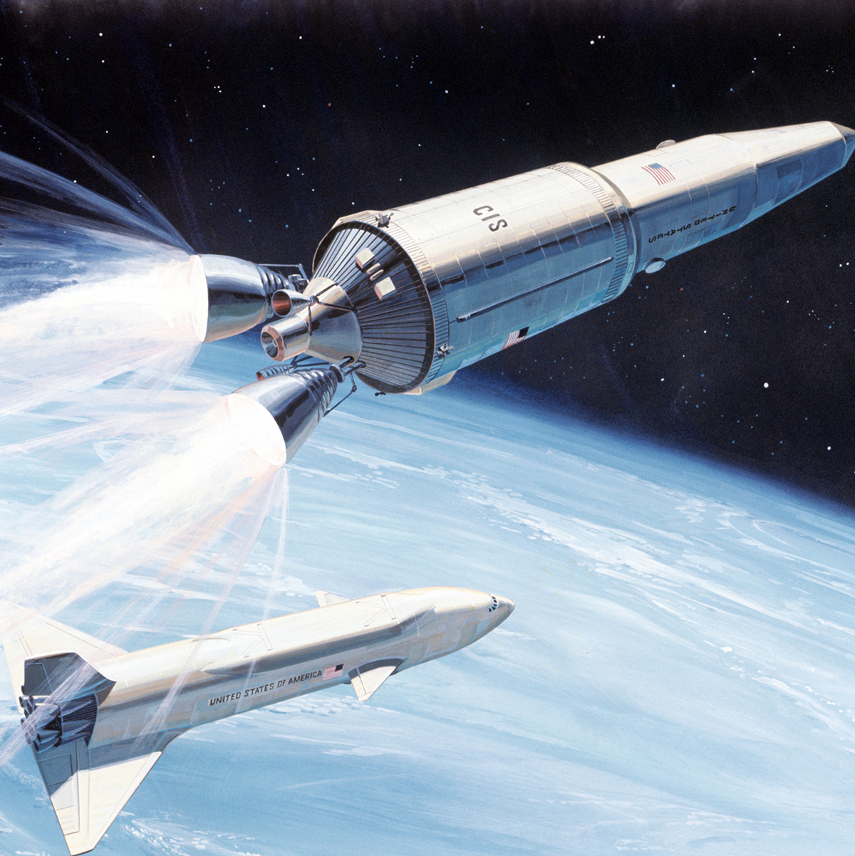
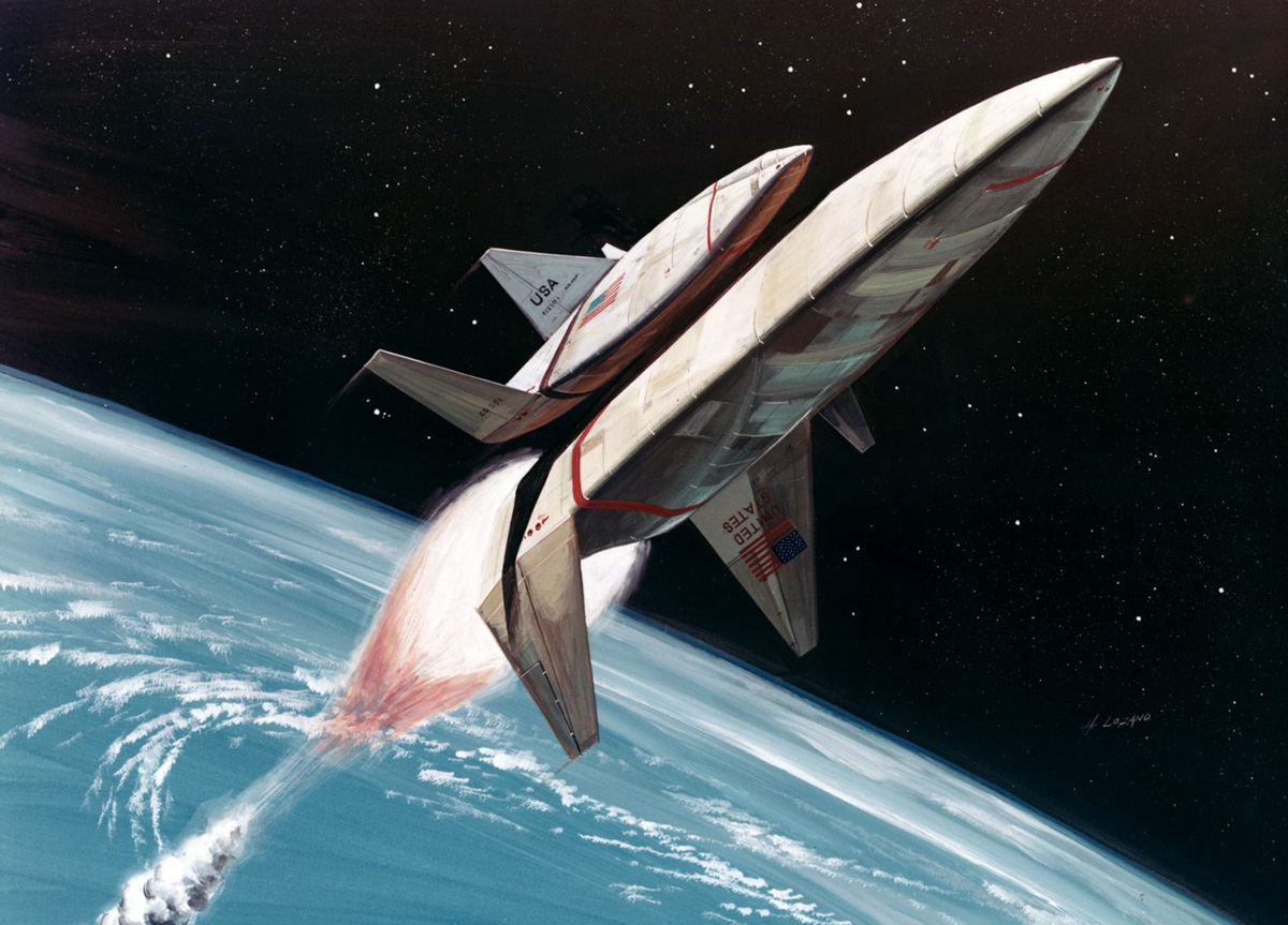
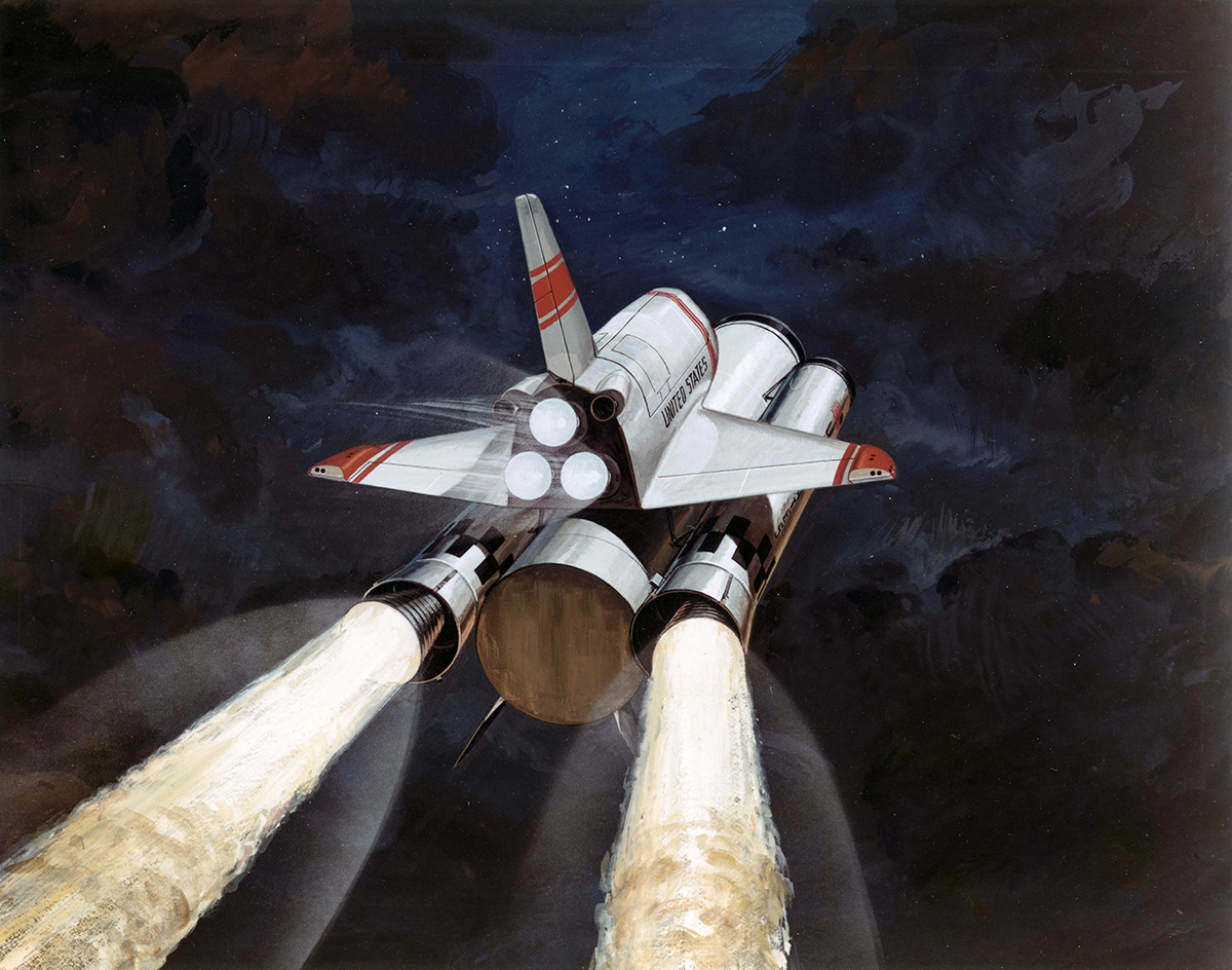
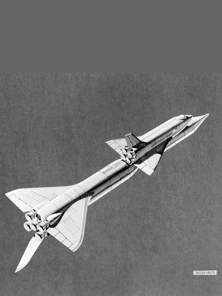
McDonnell Douglas / Martin Marietta
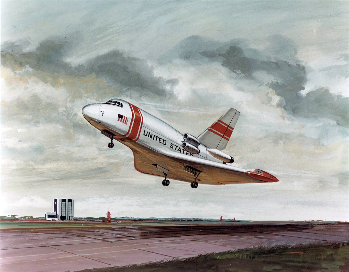
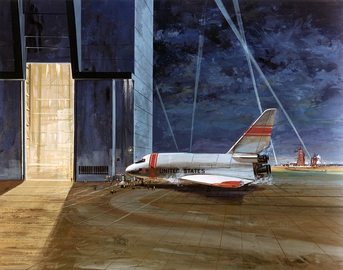
Martin Marietta’s booster was derived from an alternative Spacemaster booster concept, with jet engines mounted inside the forward canard to improve weight distribution during recovery. The all-metal orbiter featured a large delta wing and a single vertical stabilizer.
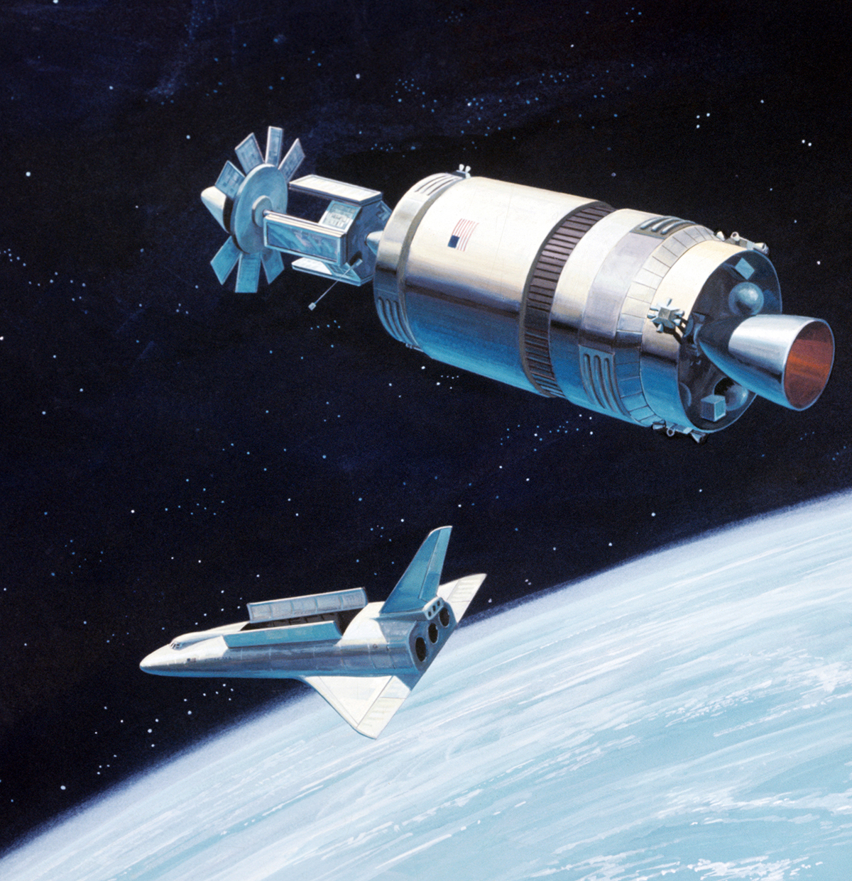
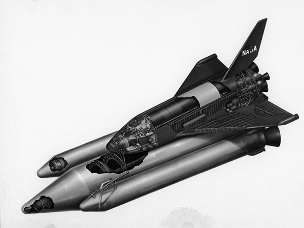
North American / General Dynamics
The NAR 130 straight-wing low cross-range design remained as a secondary option as late as 1971.
NAR 134-B was a high cross-range vehicle with a payload capacity of 9,072kg, capable of making powered or unpowered glide landings.
North American’s NAR 161-B orbiter carried a crew of two and up to ten passengers in a forward module. Four deployable jet engines mounted on top of the fuselage gave it a go-around capability. General Dynamic’s B9U booster was a significant evolution of its B8D concept. The straight wing was replaced with a delta wing to improve stability through all phases of the flight. The landing jets were moved from the nose back to the wing to reduce drag.
Alternate Space Shuttle Concepts
Chrysler
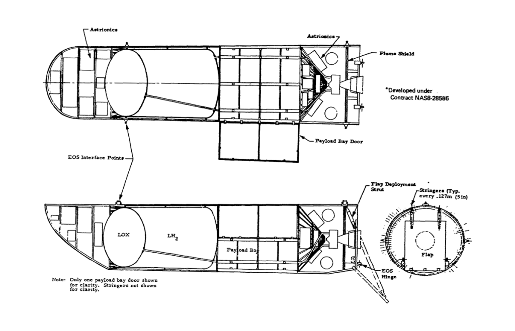
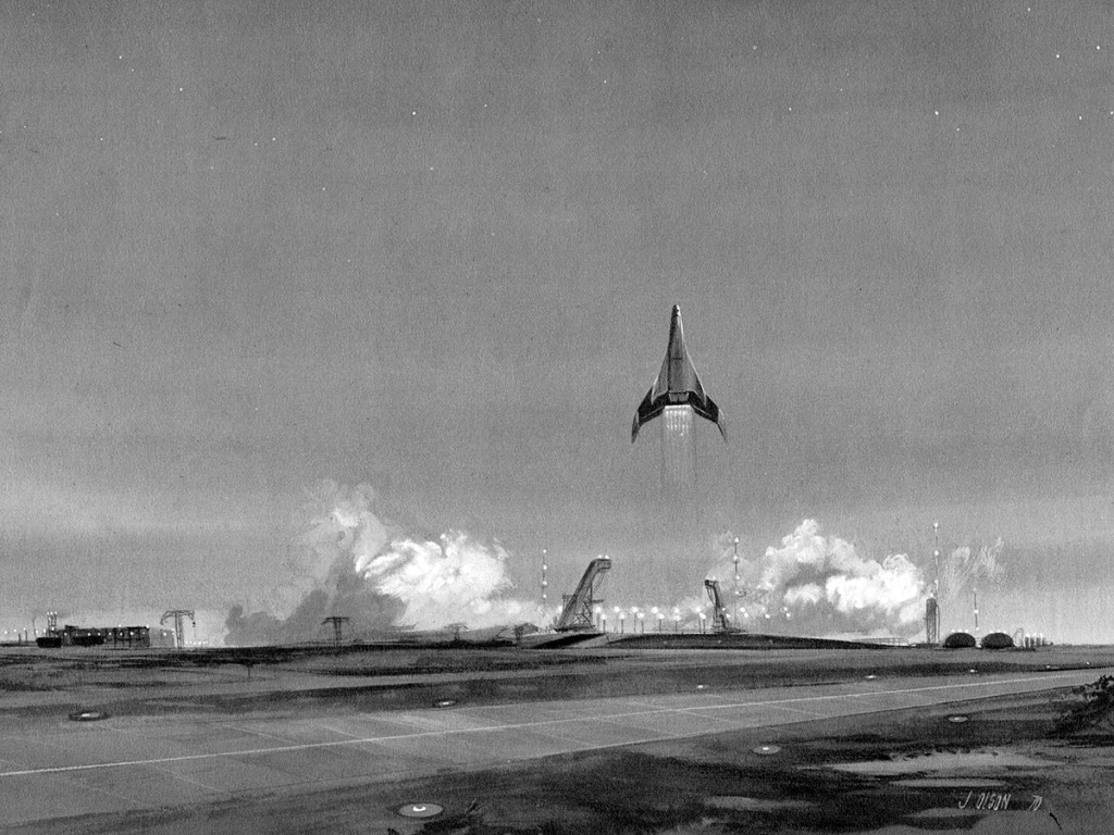
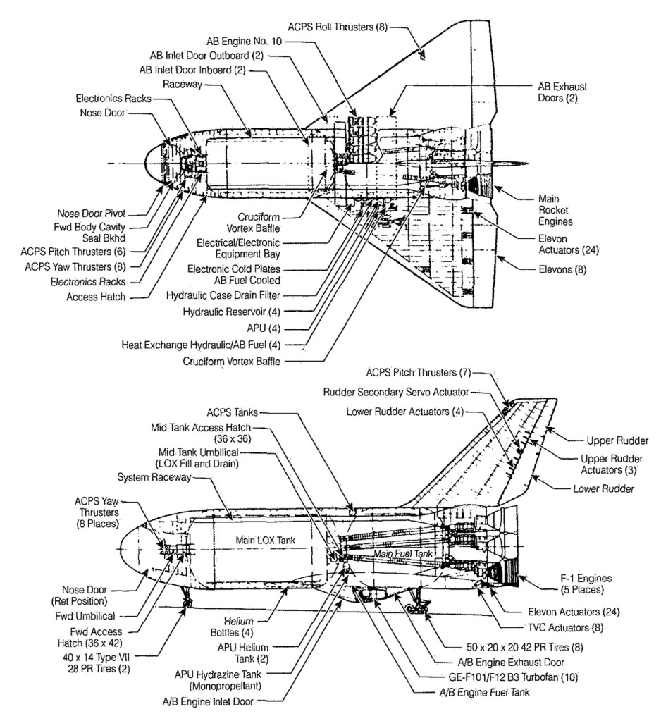
Chrysler’s Single-stage Earth-orbital reusable Vehicle (SERV) was a launch system capable of carrying up to 125,000 lbs of cargo. SERV had a large conical body with a rounded base, covered with ablative screw-on panels. A twelve module LH2/LOX aerospike engine was used during ascent, a ring of jet engines slowed the vehicle’s descent prior to touchdown. The original proposal used a lifting body spaceplane based on the HL-10 called MURP to support manned missions. A later version paired SERV with a personnel module based on the Apollo CSM.
After partnering with Boeing for a failed Phase B bid, Lockheed was awarded a contract under the Alternate Space Shuttle Concepts (ASSC) study in July 1970. The study focused on partially expendable designs as a fallback should the TSTO configurations prove too challenging or costly.
Boeing / Grumman
In December 1970 Grumman and Boeing received a contract to study two-stage-to-orbit shuttle configurations using both internal and external liquid hydrogen tanks. In review with NASA, Boeing and Grumman demonstrated that equipping the orbiter with an external drop-tank would lead to a significant reduction in the weight, size, development risk and cost of both vehicles. In April NASA authorized Boeing and Grumman to make a detailed study of the most promising configuration: a three-engine orbiter with an external liquid hydrogen tank and heat-sink booster.
May 1971 – Nixon Ruins Everything
NASA’s budget is capped by the Office of Management of the Budget for the next five years, effectively ending development of a fully reusable shuttle.
September 1971 – Phase B Prime
McDonnell Douglas and North American Rockwell both received contract extensions in March 1971 to study the impact of Grumman’s drop tank concept on their Phase B designs.
While the LS-200 design had been shelved, Lockheed received funds to continue working on drop-tank and solid rocket booster configurations.
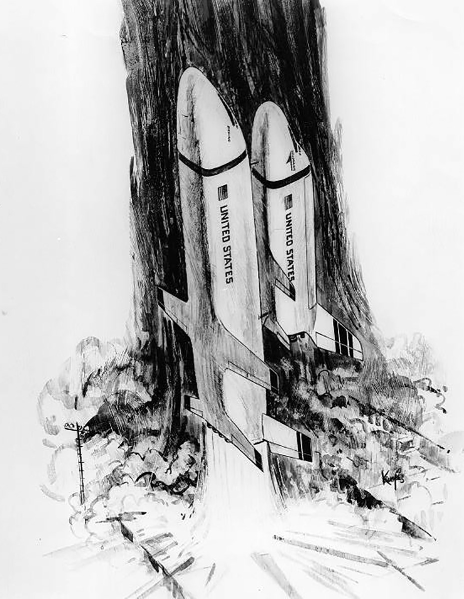
Fully-reusable shuttle orbiter with the S-IC used as an interim first stage. Painting by Grumman artist Craig Kavafes.
Boeing and Grumman investigated the Saturn S-1C interim booster concept as well as various combinations of drop tanks and boosters. Boeing also unveiled a shuttle booster design in August 1971 dubbed RS-1C, which would have put wings, landing gear and jet engines on the S-1C booster, transforming it into a flyback booster.
Winged S-IC stage. (Boeing)
October 1971 – Phase C/D Request for Proposal
RFPs were sent to Grumman / Boeing, McDonnell Douglas / Martin Marrietta, and North American Rockwell for final proposals for Shuttle full-scale development.
November 1971 – Phase B Double Prime
Grumman / Boeing, Lockheed, McDonnell Douglas / Martin Marrietta, and North American Rockwell were issued contracts to study lower cost booster concepts: a fully recoverable booster stage, a modified Saturn V stage to serve as a flyback booster, and solid rocket motors.
March 1972 – Orbiter and Integration Systems
The RFP for development of the orbiters and integration systems was released on March 17, 1972.
“As a design objective,” the RFP stated, “the Space Shuttle System should be capable of use for a minimum of 10 years, and each Orbiter Vehicle shall be capable of low cost refurbishment and maintenance for as many as 500 reuses.”
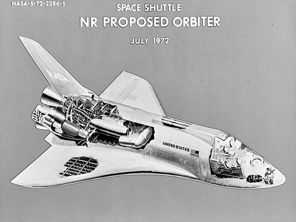
Final proposals by (left) North American Rockwell and (right) McDonnell Douglas.
The responses were due on May 12, and four companies replied: Grumman, Lockheed, McDonnell Douglas and North American Rockwell.
Grumman
Grumman gained the highest score in the technical areas. Its structural layouts showed a thorough understanding of potential problems and positive solutions. Grumman, however, was less outstanding in cost and management, the proposed cost was higher than NASA liked.
Lockheed
Lockheed’s bid ranked fourth in the competition, it was heavy and NASA Administrator James Fletcher considered that its design had “unnecessary complexity.” Lockheed was also was the only bidder with no experience in building piloted spacecraft
McDonnell Douglas
The final McDonnell Douglas proposal projected a relatively high cost, and showed technical weaknesses. The provisions in the proposal for maintainability of the Shuttle failed to adequately make use of the expertise Douglas had gained building the DC-10 airliner. McDonnell Douglas came away ranked third in the competition.
North American Rockwell
North American’s concept showed weaknesses, such as a crew cabin that would be difficult to build, but the design provided the lightest dry weight of any of the designs submitted, at the lowest cost of the four.
July 1973 – RFP for SRM
On July 16, 1973, the RFP for design and development of the SRM was issued to Aerojet Solid Propulsion, Lockheed, Thiokol, and United Technologies. NASA selected the Thiokol Chemical Company.
Volume IV: Accessing Space Edited by John M. Logsdon, with Ray A. Williamson, Roger D. Launius, Russell J. Acker, Stephen J. Garber, and Jonathan L. Friedman. 1999
I honestly thought knocking up an illustrated history of the shuttle would take me an afternoon, and I was wrong. Very wrong. There’s a lots of backstory. But if we’re going to talk about this, you need to know about that, and the other thing, know what I mean?
The thing with the shuttle is, there is no great speech that spurred a nation forward, no watershed moment, no great need. It’s hard to know where to start, where it begins. Instead, the first space worthy orbiter was a coalescent of decades of half-starts, what-ifs, and “if we can’t have that, can we have this?” It has no father or mother, but it has uncles, aunts, and lots of those cousins you’re not supposed to talk about at the dinner table.
So here is what I think is a mostly correct, potted history of the Space Shuttle. It is neither exhaustive, nor authoritative, but the artwork is beautiful and that’s why you’re here. Right?
Background
Writing about the space program is like writing an Indiana Jones movie. It just doesn’t work without Nazis. So, we’ll start the story in 1936 with some Nazis….
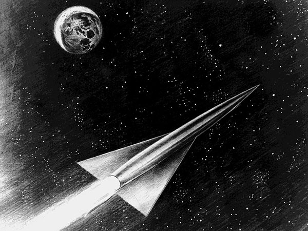
Silbervogel 1936-1944
In the mid-thirties, an Austrian engineer named Eugen Sänger – a Nazi – published a series of articles on rocket-powered flight for the Austrian journal Flug. Those articles attracted the attention of the Reichsluftfahrtministerium, the Reich’s Aviation Ministry. Sänger’s ideas had potential for the Amerikabomber project, an initiative to obtain a strategic bomber capable of striking the United States from Germany. The RLM gave Sänger his very own research institute near Braunschweig where, aided by mathematician Irene Bredt, he developed a sub-orbital rocket bomber, the Silbervogel. Launched from a rocket-powered sled at 1,200mph, the Silbervogel would climb under its own power to an altitude of approximately 90 miles, accelerating to approximately 13,500mph. As it glided back into the stratosphere, the increasing air density would generate lift against the fuselage causing it to bounce and regain altitude. Aerodynamic drag would begin to slow the vehicle, each bounce being shallower than the last, but the vehicle would still be able to cover vast distances.
While the Reich Air Ministry rejected Sänger’s 1941 initial report due to its size and complexity, a greatly reduced version of that report submitted to the RLM in 1944 represents the first serious proposal for a vehicle capable of reaching the edge of space.
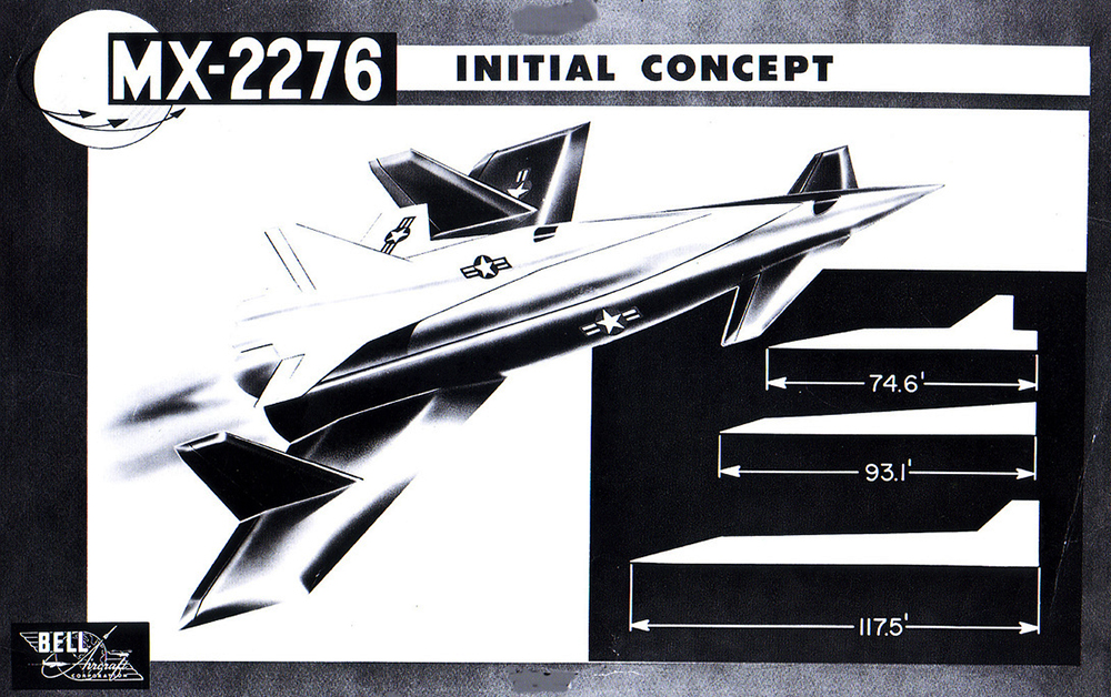
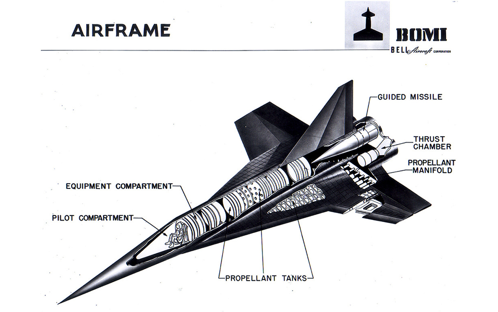
BoMi 1952-1956
In 1952, Walter Dornberger and Krafft Ehrikke at Bell Aircraft proposed a vehicle based on Sanger and Bredt’s research. Dornberger had led Nazi Germany’s V-2 program and other projects at Peenemünde, where Ehrikke had worked as a propulsion engineer. In essence, their proposal was a vertically launched version of the Silbervogel, known as Bomber Missile or Bomi. By 1956, BoMi had evolved into three separate programs:
RoBo, or Rocket Bomber, an updated version of BoMi.
Brass Bell, a long-range reconnaissance version.
Hywards (Hypersonic Weapons Research and Development Supporting system), a smaller prototype system to develop the technologies needed for Robo and Brass Bell.
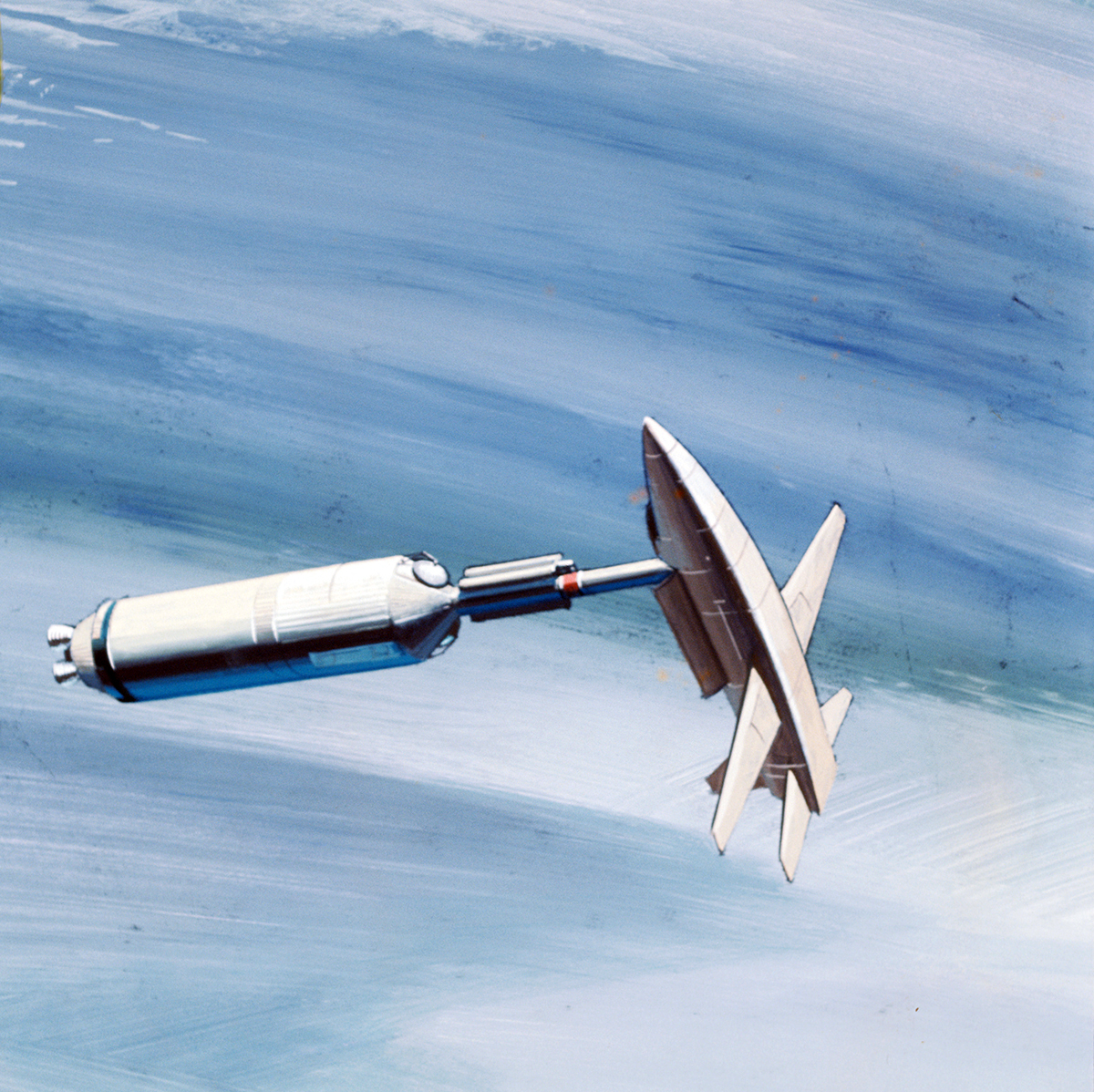
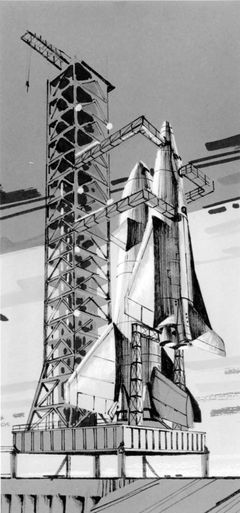
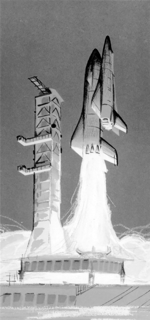
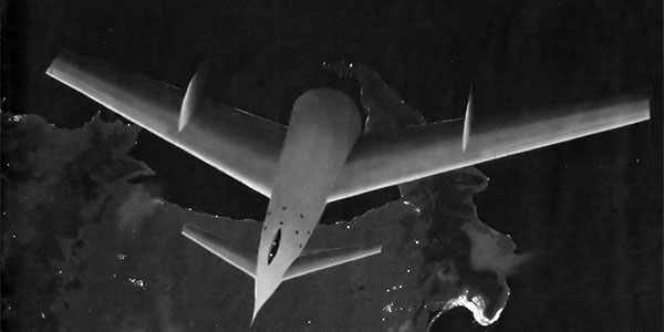
Von Braun Ferry Rocket – 1952
For the Colliers series of articles and subsequent books, Von Braun proposed a sleeker, more elegant version of a launch vehicle he’d conceived of in 1948.
The three-stage rocket lauched vertically, after a short interval the autopilot would tilt the rocket to a shallow angle while still climbing. At an altitude of 24.9 miles the first stage separated, a fine steel-mesh ribbon parachute deployed, slowing the tail section towards a gentle water landing. The second stage separated when the vehicle reached an altitude of 40 miles. The cabin-equipped reusable third stage would continue under its own power to an altitude of 63.3 miles when its engines would cut out , momentum carrying it to orbit. At an altitude of 1,075 miles, a 15 second engine burn would stabilize its orbit. Reentering tail first to an altitude of approximately 50 miles, the pilot would level off, holding attitude to allow air friction to slow the vehicle from 13,300 mph to 5,760 mph. At an altitude of 15 miles, now travelling at 750mph, the pilot would begin a series of descending turns toward the landing site, touching down at approximately 65mph.The first and second stages would be recovered at sea for refit and reuse.
Goodyear METEOR – 1954
In 1954 Goodyear Aerospace’s Darrell Romick and two colleagues introduced a concept model of a three-stage spaceplane, the third stage achieving earth orbit, at the annual conference of the American Rocket Society. Each stage would contain landing gear and a crew of its own, allowing each to be piloted to landing for reuse. Launched at White Sands, the first booster stage would separate 300 miles downrange at an altitude of 24 miles, the second stage 700 miles farther at 41 miles, with the third stage continuing to orbit.
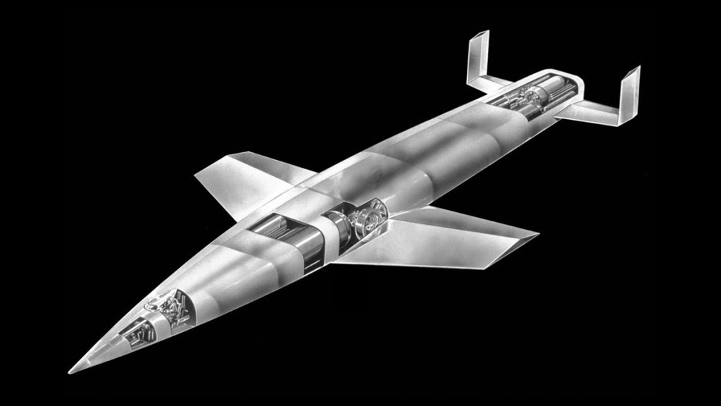
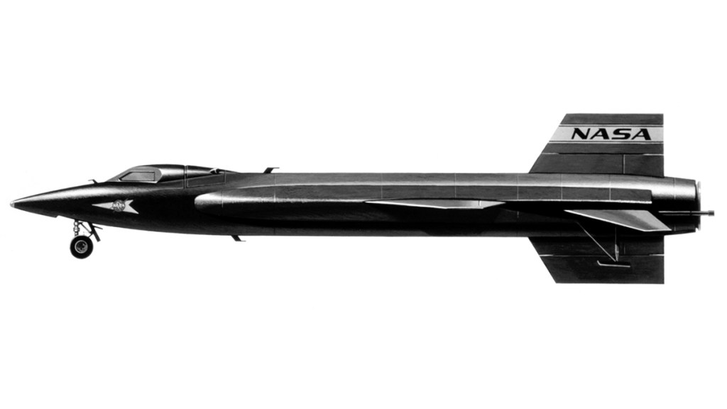
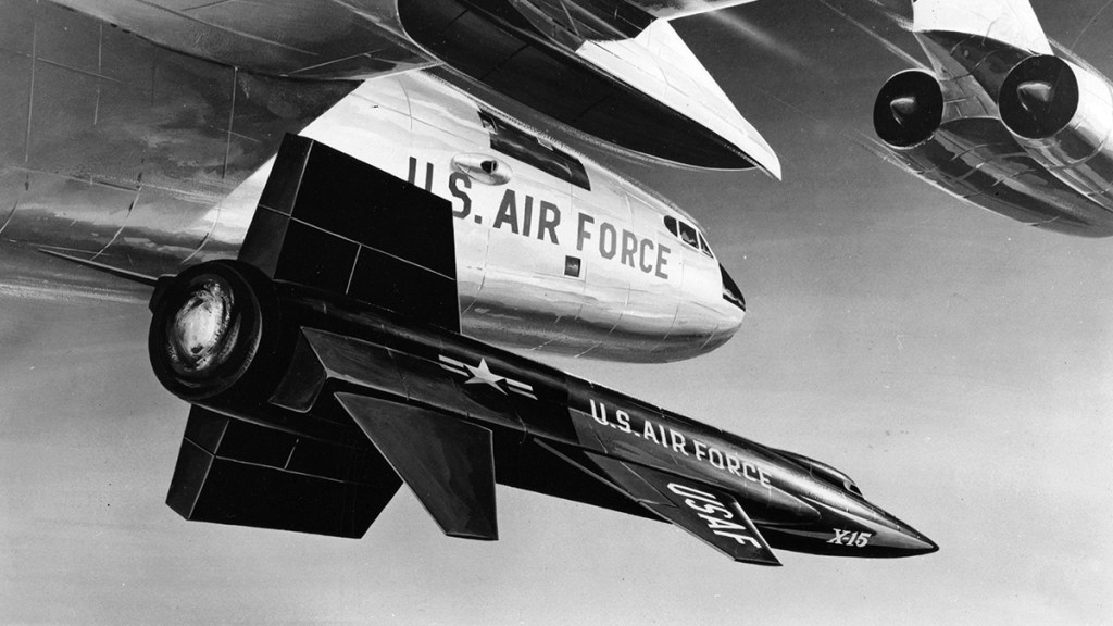
X-15A 1954 – 1968
The X-15 was based on a concept study prepared by Dornberger for the NACA on hypersonic research aircraft. RFPs were published in 1954 for the airframe, and 1955 for the engine. North American Aviation won the contract for the airframe in 1955, Reaction Motors was contracted to build the engines in 1956. The aircraft first flew in 1959, and over the course of the program eight of its twelve pilots earned astronaut wings for flights above the Kármán line. As early as 1957, an orbital version of the X15 was considered by the Air Research and Development Command (ARDC) at Wright Field based on a proposal by North American engineer Harrison Storms.
Convair Shuttlecraft – 1957
Having moved to the Astronautics Division of Convair, Krafft Ehricke proposed a three-stage shuttlecraft capable of carrying a pilot and four passengers on ferry missions to resupply Earth satellites.
“Ready for launching, the satelloid would be a three-stage rocket, with the third stage having a deltalike wing and a sealed cabin outfitted for flights up to a week. After the first and second stages were fired and dropped, the third stage would take up its orbital path. To return to earth, the satelloid would be stalled down through the atmosphere at a very high of attack to reduce forward speed and prevent excessive heating. Even so, skin temperatures of around 2000 degrees would be experience and a multiwalled cabin would be required to keep the occupants cool.“
-Popular Mechanics, Mar, 1957
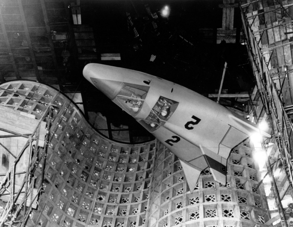
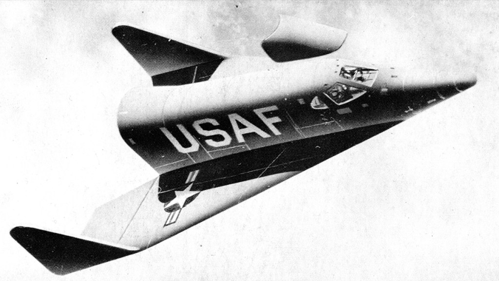
X-20 Dyna-Soar 1957-1963
Left: After aerobraking in the atmosphere, the opaque heatshield protecting the window is jettisoned so the pilot can see the fucking ground. Right: Bell Aircraft artist concept.
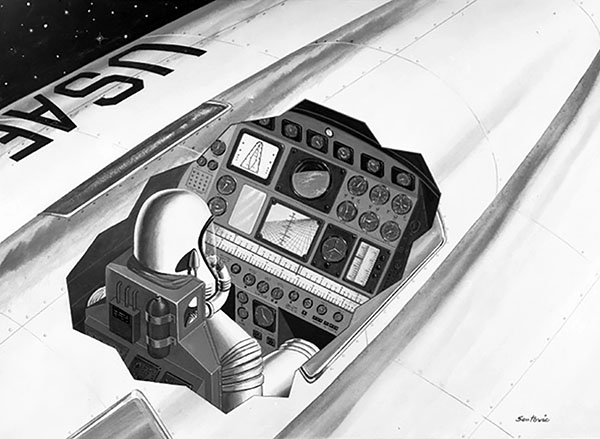
After the launch of Sputnik in October 1957, the USAF Air Research and Development Command (ARDC) consolidated the RoBo, Brass Bell, and Hywards studies into the Dyna-Soar project, or Weapons System 464L. In 1958 nine contractors tendered bids for the project, the field eventually being narrowed to just Bell and Boeing. Despite six years of continuous research at Bell, the contract was awarded to Boeing in June of 1959. The overall design was outlined by Boeing in 1960. The vehicle would have a tail-less low-wing delta shape. A single pilot sat at the front, with an equipment bay behind containing reconnaissance equipment, weapons, or a four-person mid-deck depending on the mission. The frame and upper surfaces would be constructed of René 41, a nickel-based alloy, the lower surfaces covered by molybdenum sheets placed over insulated René 41. An expendable Martin Marietta upper stage attached aft of the vehicle would allow orbital maneuver and a launch abort capability.
Now designated X-20, Dyna-Soar was unveiled to the public at an event in Las Vegas in 1962. Eight months before drop tests were to begin, politics, and the lack of clarity over its mission led to its cancellation in December 1963 by then Secretary of Defense, Robert McNamara.
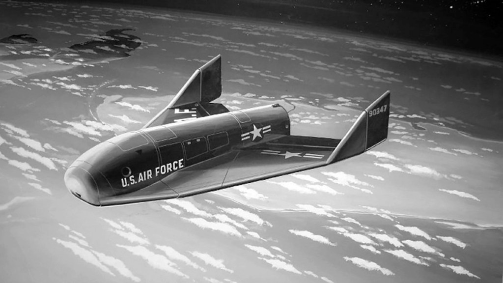
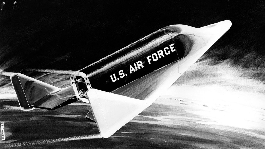
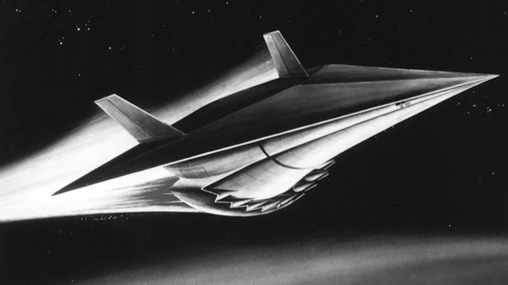
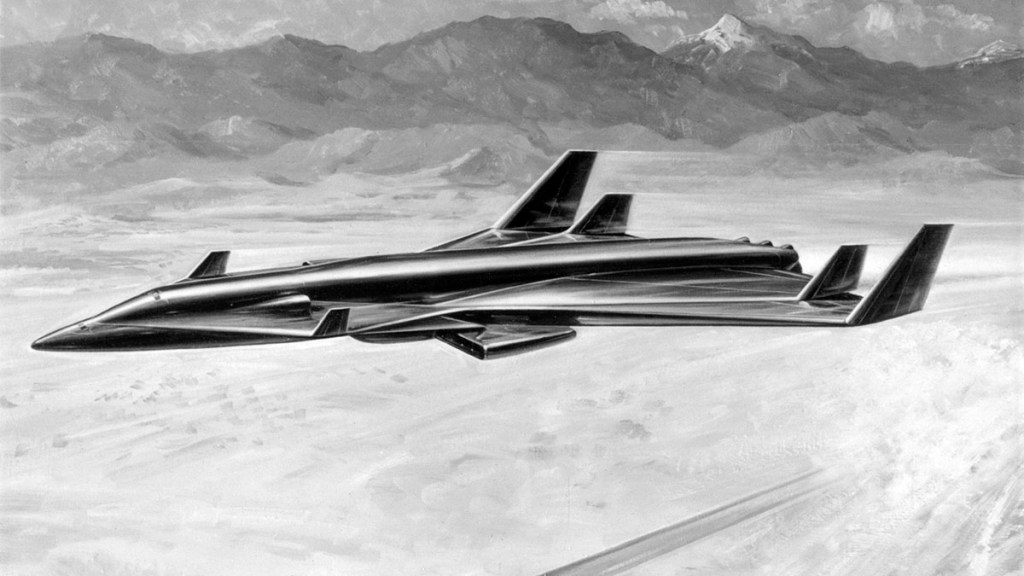
Aerospaceplane 1957-1963
An attempt to develop an air-breathing single-stage-to orbit spaceplane at Wright-Patterson AFB, led to a 1957 DoD funded for a recoverable launch booster. By 1959, it had evolved into the Recoverable Orbital Launch System or (ROLS), a single-stage-to-orbit horizontal-take-off-and-landing vehicle. A liquid air cycle engine (LACES) would liquefy air on its ascent to use as an oxidizer for rocket fuel at altitude. Further testing revealed that better performance could be achieved by extracting pure oxygen from the liquified air. Research contracts were issued to Marquardt and General Dynamics to develop the Air Collection and Enrichment System (ACES) with Garret AirResearch designing and building the heat exchanger.
Boeing, Douglas, Convair, Lockheed, Goodyear, North American, and Republic were awarded study contracts to develop a single-stage-to-orbit (SSTO) vehicle capable of horizontal take-off and landing. With a crew of three, and a twelve-meter cargo bay, the vehicle was to be operational by 1970. Developmental realities forced the Air Force to drop its requirement for a single-stage vehicle in 1962. In June 1963 Douglas, General Dynamics, and North American each received funds for continued study, with Martin receiving a contract from the Air Force Flight Dynamics Laboratory to build a full-scale wing-fuselage structure. In October that year, the USAF SAB concluded that the existing state-of-the-art was insufficient to develop the Aerospaceplane in a reasonable time and did not request funding the following year.
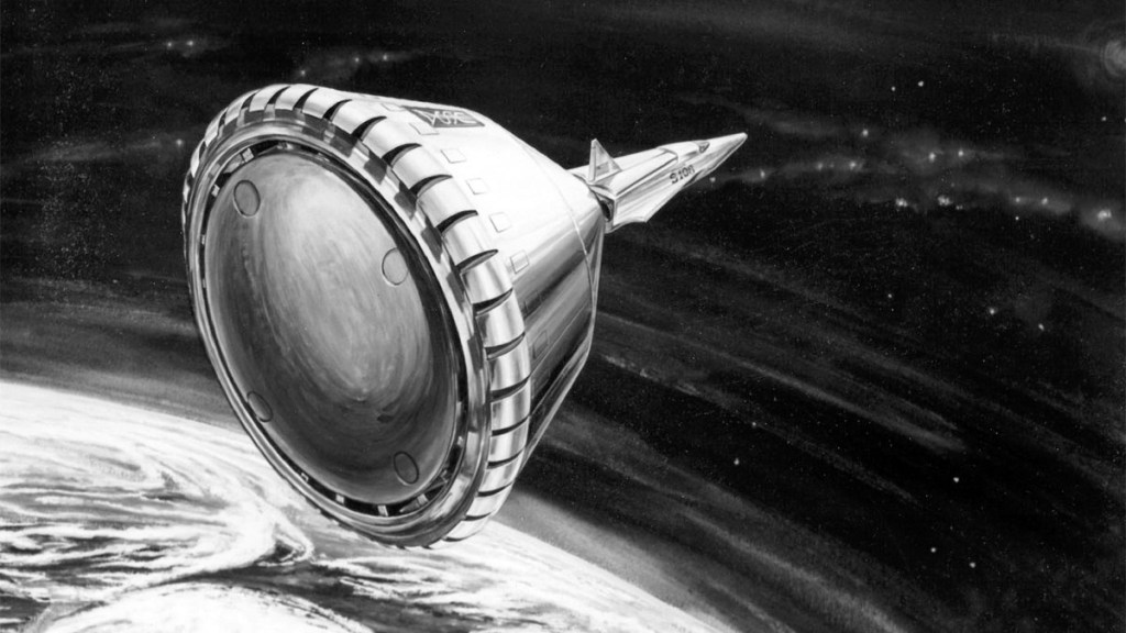
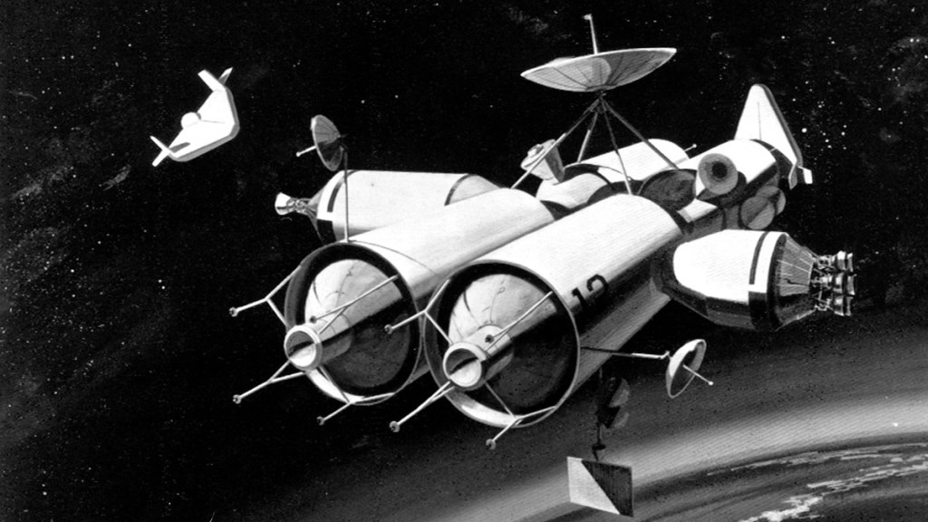
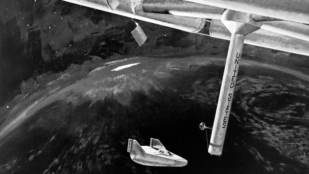
ATLAS Orbital System – 1958
Less than a year after the Atlas ICBM began flight tests Krafft Ehricke proposed an ingenious solution to building an orbiting space station which, as Mercury had yet to fly, no one really needed. Since no booster capable of delivering a space station to orbit existed, Ehricke proposed modifying the forward propellant tank1 of an Atlas to accept an inflatable rubber nylon structure, providing insulation, and subdividing the tank into rooms. The space station’s own booster would become it; the station. The four-story habitat would accommodate a laboratory, sleeping quarters, a kitchen/day room and a khazi. Fitting out the Outpost was expected to take about a week: the first four-man crew would rendezvous with the spent rocket in a personnel module comprising of two manned gliders boosted by a primary Atlas stage and a second Centaur stage. An unmanned cargo module carrying supplies would arrive separately.
After installing battery power, water, and oxygen systems delivered by an unmanned cargo module the crew would depart. Subsequent crews would deliver and inflate the pressurized habitat module and complete the fit out. The final crew would install a SNAP-2 nuclear reactor and fire vernier thrusters, spinning the station to create artificial gravity, making it operational.
National Aeronautics and Space Act 1958
The Eisenhower Administration split the United States’ military and civil spaceflight programs, which were organized together under Defense Department’s Advanced Research Projects Agency (DARPA).
The National Aeronautics and Space Administration (NASA) was established in July, replacing the National Advisory Committee for Aeronautics (NACA), giving the United States space development effort a distinctly civilian orientation. NASA absorbed the core of NACA employees, as well as the Naval Research Laboratory’s Project Vanguard, the Army’s Jet Propulsion Laboratory, and the Army Ballistic Missile Agency.
Space Task Group 1958
In November, a working group of NASA engineers was established to manage Project Mercury and future US space endeavors.
NASA Studies 1962-1964
In 1962 NASA began to fund studies for space station logistics vehicles, including the “Reusable Ten Ton Orbital Carrier Vehicle” or RTTOCV.
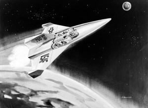
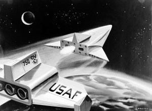
Douglas Astro
Douglas Astro as visualized by (left) Ron Simpson and (right) Ken Hodges. The Simpson painting was reproduced on a lenticular airmail stamp issued by the Kingdom of Bhutan in 1970.
The Astro was a VTHL TSTO system designed to support space station operations using designed around existing hardware from the Apollo and other US space programs.. Both stages were manned lifting body vehicles.
Lockheed RTTOCV
Lockheed proposed a two-stage winged vehicle based on a classified Air Force study it conducted in 1958 in co-operation with Hughes Aircraft. Lockheed’s final design was boosted by a sled-launched rocket plane.
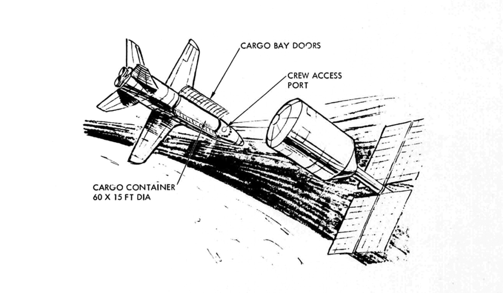
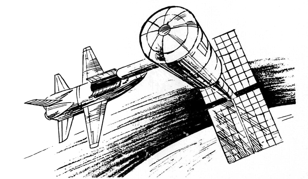
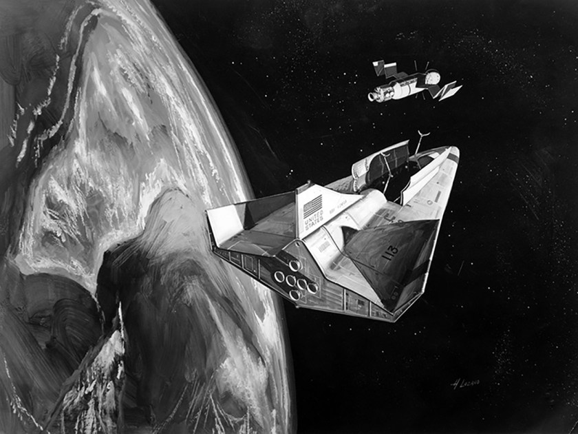
Lockheed Space Taxi
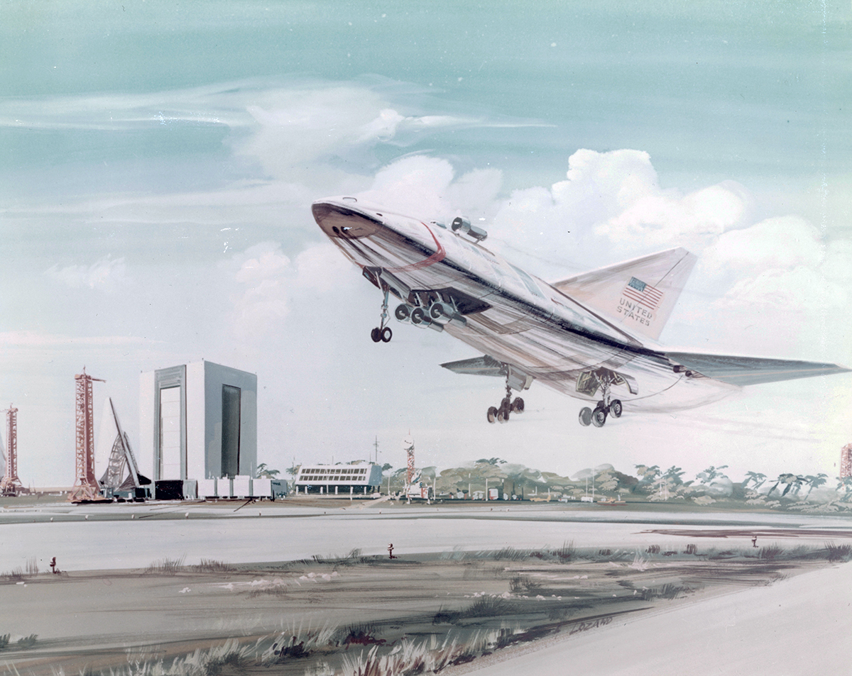
Lockheed proposed replacing the Apollo CSM with ten-man reusable spaceplane while retaining the Saturn IB booster as a means of reducing the cost of NASA’s space station, lunar base, and other activities in the seventies. Fully reusable system options included a sled-launched HTHL TSTO rocketplane or a ramjet-rocketplane deploying the interorbital Space Taxi.
McDonnell Space Plane
McDonnell’s study of 1963 proposed three vehicle options, launched on either Titan 3M or Saturn IB launch vehicles. The first two were based on McDonnell’s Gemini capsule, the latter was a winged vehicle capable of carrying a crew of two and up to four passengers.
NAA RTTOCV
North American’s final design of 1963 was a lenticular orbiter carrying two pilots and up to ten passengers.
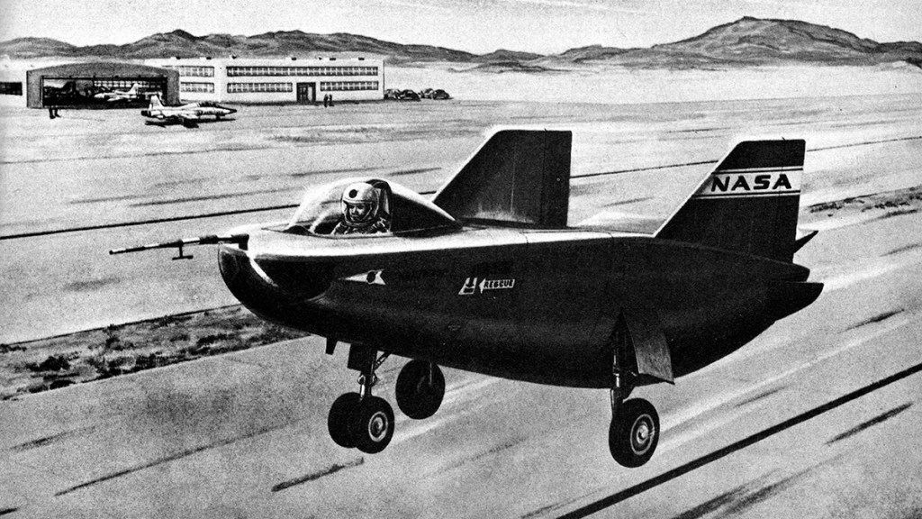
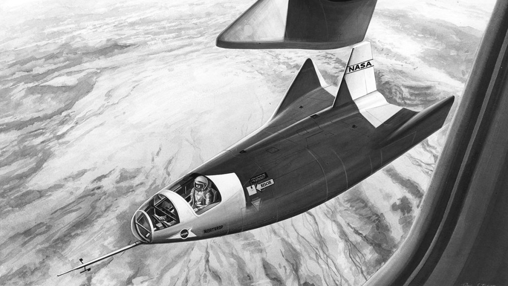
NASA Lifting Body Research 1962-1972
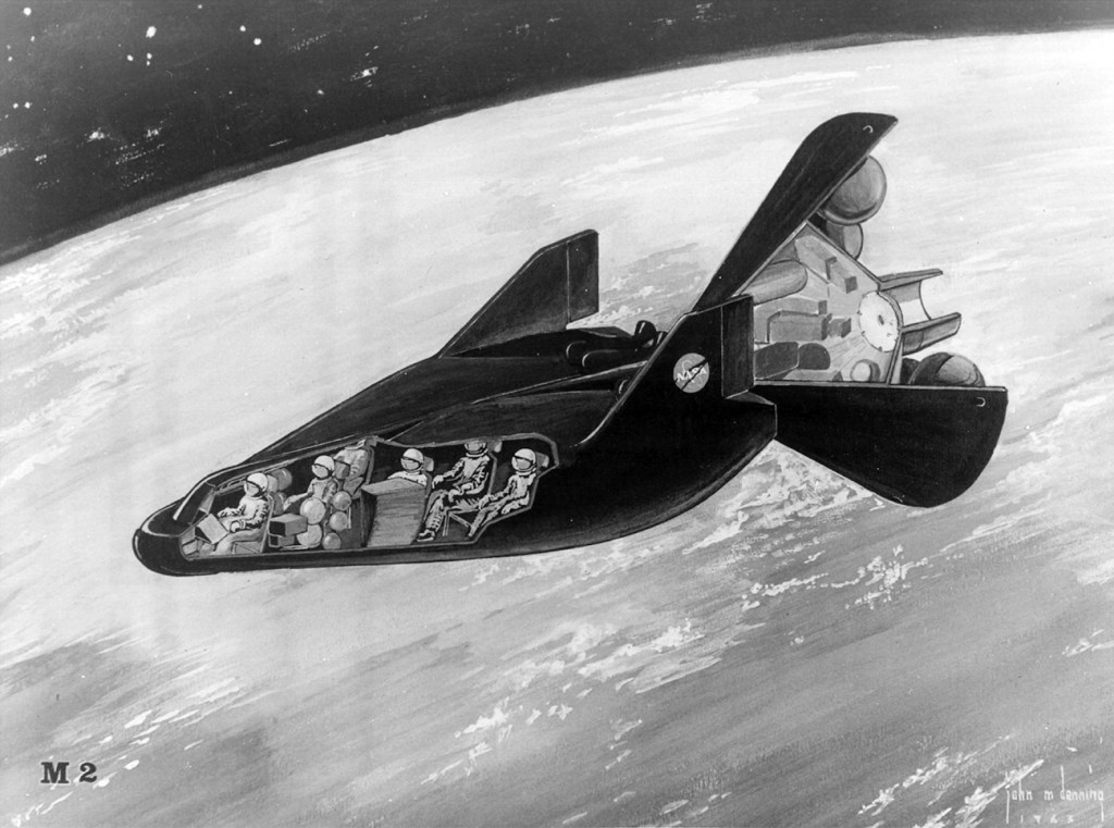
NASA M2-F1, the original lifting body aircraft was built as an in-house NASA Dryden project on a budget of $30,000. The aircraft was of tubular steel construction, covered with a mahogany plywood shell with landing gear taken from a Cessna 150. After towing the M2-F1 behind a Pontiac convertible, air tows behind a NASA C-47 began in August 1963. The success of the program led to NASA’s development and construction of two heavyweight lifting bodies, the M2-F2 and the HL-10, both built by Northrop. In 1967, the M2-F2 was severely damaged in a landing accident after an unpowered glide test. Redesigned with a third center fin to improve stability, and re-designated M2-F3, it flew again in June 1970.
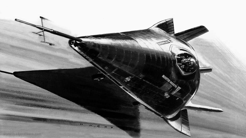
PILOT 1963-1975
Martin-Marietta X-24 painted by Wilf Hardy for Look and Learn.
The X-24 was built by Martin Aircraft Corporation as part of a joint US Airforce-NASA program called PILOT. The X-24A was the fourth lifting body design to fly, making its first flight in 1969. After 28 flights, the vehicle was returned to Martin (now Martin Marietta) and rebuilt as the X-24B, testing FDL hypersonic configurations which promised to double the hypersonic lift-to-drag ratio of the X-24A. On its own initiative, Martin Marietta built two jet-powered versions of the X-24A envisioned as training airframes, dubbed SV-5J, which were never flown.
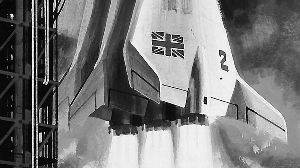
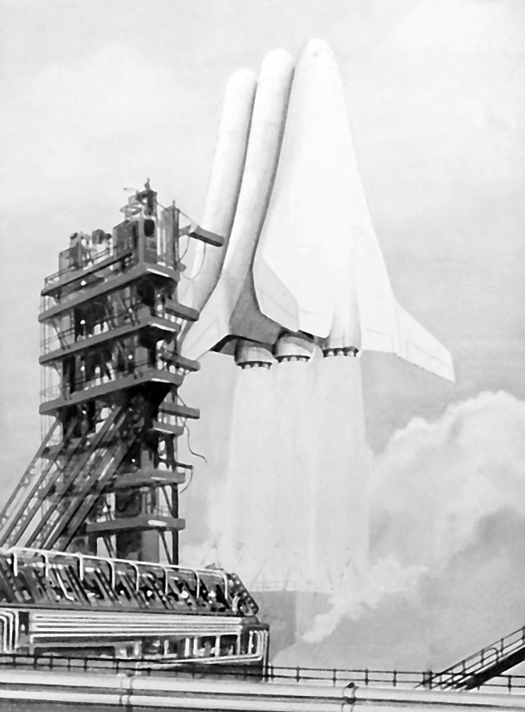
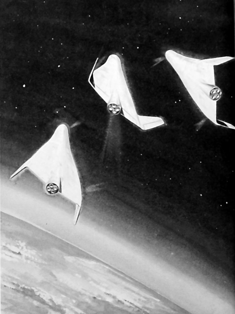
BAC MUSTARD 1964-1967
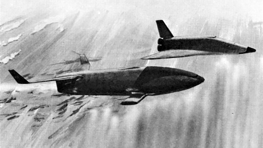
The Multi-Unit Space Transport And Recovery Device or MUSTARD was a reusable launch system concept explored by the British Aircraft Corporation. Mustard would launch vertically; the hypersonic spaceplane modules would progressively separate during ascent. The final spaceplane would be capable of achieving a sub-orbital trajectory before performing a controlled re-entry.
AACB 1965-1966
After Aerospaceplane was terminated, the USAF Flight Dynamics Laboratory began studying less ambitious spaceplane designs, which led to a series of studies funded by the joint NASA / DOD Aeronautics and Astronautics Coordinating Board. The final report was issued in 1966 and suggested that reusable launch vehicles be developed in a series of classes:
AACB Class I Partially reusable vehicle launched either by existing Titan or Saturn boosters. The vehicle would accommodate up to six astronauts, carry a payload of up to 900 kg, and be available for space station crew transfer and resupply by 1974.
AACB Class II Fully reusable, two-stage-to-orbit launch vehicle. Both stages powered by LOX/LH2 engines, the vehicles would be ready by 1978, and capable of placing a payload of 9,100 kg in orbit.
AACB Class III An advanced concept using two air breathing stages to achieve orbit. The AACB concluded that the technology to develop the Class III vehicle did not exist, and the vehicle would not be available until 1982 at the earliest.
The Class I vehicle became the preferred option of the AACB, given that it had the lowest development risk, and cost.
ILRV 1967-1968
Between 1967 and 1968, the US Air Force issued study contracts for “Integral Launch and Re-entry Vehicles” or ILRVs:
FDL ILRV
In late 1968 the USAF Flight Dynamics Laboratory proposed a stage-and-a-half concept with an external drop tank.
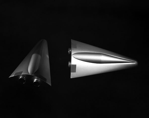
General Dynamics Triamese
General Dynamics dusted off a design originally developed for a classified 1965 USAF SAMSO project. The system was composed of three nearly identical booster / orbiter elements. Two vehicles would supply propellant for the engines of all three units during ascent. The orbital element continued to orbit with its engines fed by its own internal propellant supply.
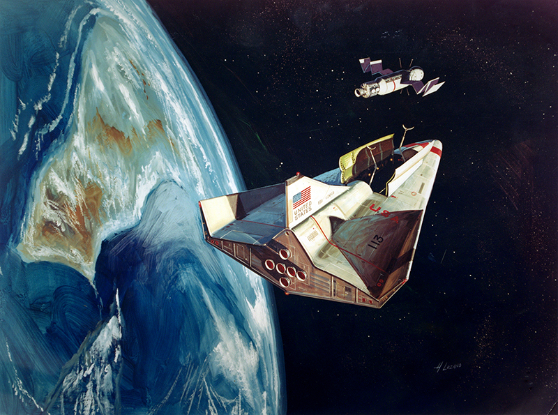
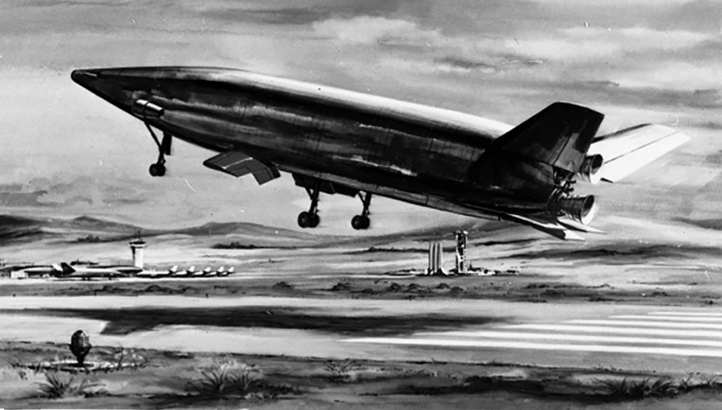
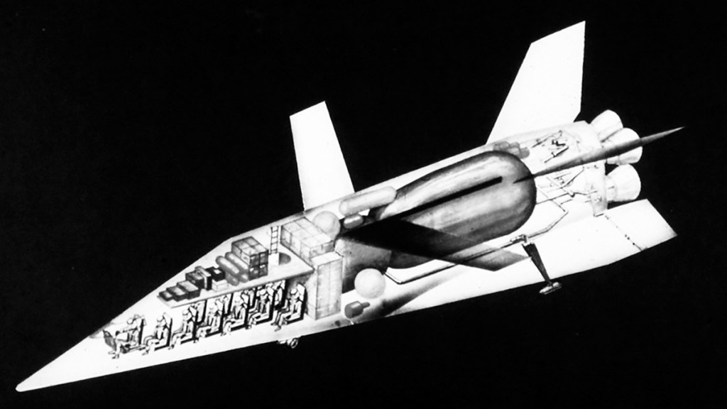
McDonnell Douglas ILRV
McDonnell Douglas proposed a wedged-shaped ILRV orbiter, equipped with fold-out wings to improve handling during approach and landing.
Lockheed Star Clipper
STAR Clipper, Lockheed’s ILRV design was an elaboration of a design proposed by Max Hunter in 1966. The vehicle was based on the X-24B, powered by a linear aerospike engine, with a wraparound drop tank. George Mueller, NASA’s Associate Administrator for Manned Space Flight, presented a downsized version of the design at a British Interplanetary Society meeting in August 1968. Mueller described the vehicle as a “space shuttle” primarily intended for space station crew transfer and resupply missions.
The problem with septuagenarians, octogenarians, and nonagenarians is that they don’t really ‘do’ social media. I guess the reason is, at that point in one’s life, your brand is pretty much established and perhaps there are better things to do with one’s time.
Fair.
But that’s also the first hurdle I faced on the piece I wrote about Alvarez. I did some research, but it’s such a common name in Southern California that looking for a M. Alvarez in Downey California yielded hundreds of results on social media, and none of them were the right person. I hoped that maybe, just maybe, the article would fire up a synapse or two in a stranger. It worked out well for the Sentovic piece, right?
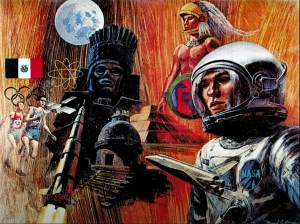
Anyway, a couple of days after I published the article, I got an email from Mike. The story had stirred a synapse, and he remembered an article he’d read written by Apollo engineer Anthony Vidana called “I Remember Bldg. 290.” In the article, the author recalls a career at North American Aviation, presenting a fascinating memoir that includes a story about him and others trying to push NASA towards hiring a Mexican American astronaut. As part of the campaign, he’d used some of his clout at Rockwell to get a company artist to create a painting.
Anthony recalls, “I envisioned an astronaut and an Aztec with similar head gear and an Aztec pyramid, observatory, moon and statue in the background. The artist, Alvarez, added the Space Shuttle and the Mexican Olympics as an added touch.”
Alvarez!
The article includes a thumbnail of the painting – subsequently gifted to the President of Mexico – and it’s gorgeous but low resolution, and the signature is pretty much cropped out, but it’s there and it’s by Alvarez for sure. I can make out an M and maybe an L. Mike emails me, “At the risk of stereotyping, could it be Miguel or Manuel?” It could, but perhaps we’re reaching? Look at it long enough and we’ll start to see what we want to see.
I reached out to Anthony Vidana, who has a social media presence. Sadly no success.
In the meantime Mike kept digging and found another clue, a Directory of Spanish Surnamed and Native Americans in Science and Engineering, published in 1978 by San Diego City Schools. One of the entries is a Manuel Alvarez working at North American Rockwell.
1. Jake I. Al4irjd (b. New Mexico) /North American Rockwell 2. Humberto F. Alcantar (b. California), North American Rockwell, NASA Space Division 3. Manuel E. Alvarez (b. California), North American Rockwell
And there’s more – and I’d completely missed this while trying to track down Mr. Vidana – Anthony has a YouTube channel, where he shared a delightful video in 2020. The clip retells the story of The Mexican Astronaut, and mentions the artist again, this time using his full name.
Manuel E. Alvarez.
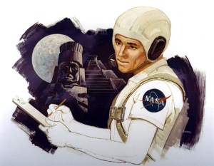
Above: A screengrab from Anthony’s video. Enlarged, the signature is pretty clear. Below: An early study for the painting, the astronaut is clearly modelled on a yet-to-be-born Ryan Reynolds.
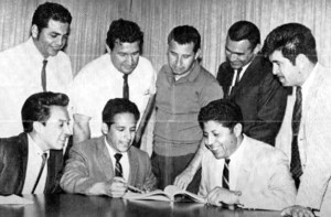
Below: Last but not least, and also grabbed from the video.
MOTIVATION OCCUPATION – Space Division and Autonetics employees comprise the board of directors for the Youth Incentive Through Motivation organization combating the school “drop out” problem. Planning activities are, seated, Fred Rodriguez, Robert Arabelo, Autonetics; Manny Alvarez, Space; standing, Hank Martinez, Phil Padilla, Jake Alarid, Joe Gomez, Ted Garcia, Space.
If by any chance you’re Manuel Alvarez and you’re reading this, or perhaps he’s your dad, or an uncle, or your grandpa; please reach out to me. I’d love to talk to you, and I know there are a lot of people who’d love to know more about you and your career.
If you have a minute, take a look at Anthony’s channel and y’know, ‘smash the like button’. Hopefully he’ll be encouraged to release more videos.
Mike, thanks again, you’re a legend!
Image credit: North American Rockwell Image source: Anthony Vidana