
Image credit: North American Rockwell
Images: NASA, Mike Acs
Image credit: North American Rockwell
Images: NASA, Mike Acs
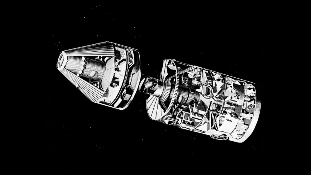
Image credit: McDonnell Douglas
Image source: Numbers Station
Planetary Illustrations (artists’ concepts)
Image credit: Krafft Ehricke Papers / North American Rockwell
Image source: NASM
A huge telescope in this astronomy module can be docked with the Space Station ’80 to give scientists the best view of stars ever possible.
Space Station ’80
by Lou Jacobs, Jr.
Hawthorn Books, 1973
Image credit: NASA
Image source: Numbers Station
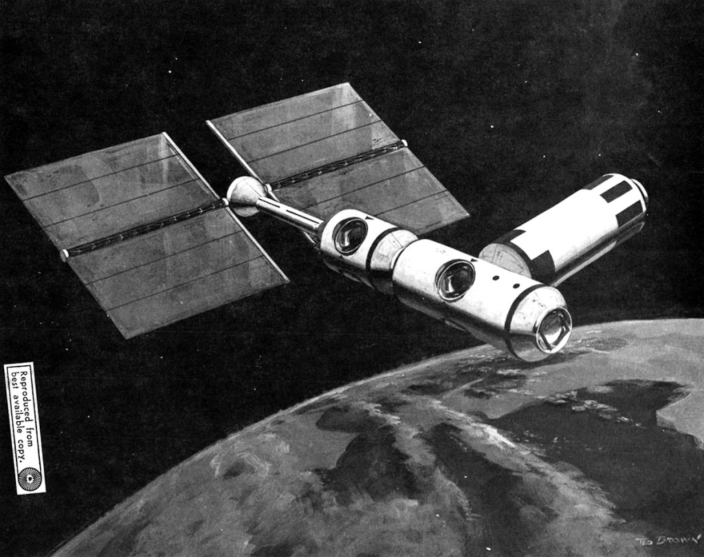
Image credit: McDonnell Douglas
File source: NASA NTRS
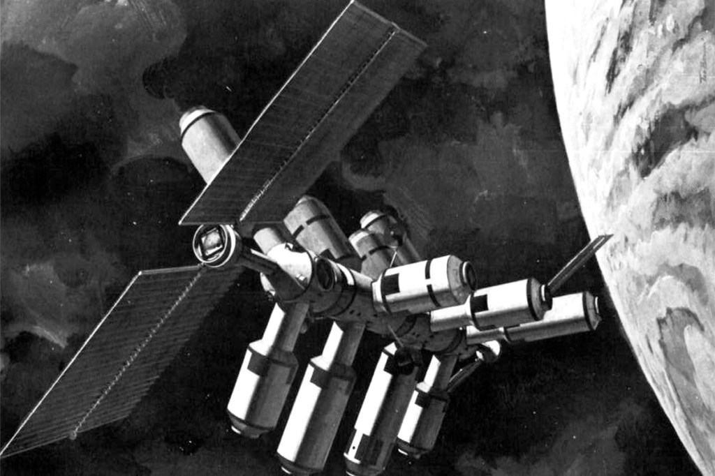
Image credit: McDonnell Douglas
File source: NASA NTRS
Selected Plates From:
June 3 Thru 5, 1970
Space Divison
North American Rockwell
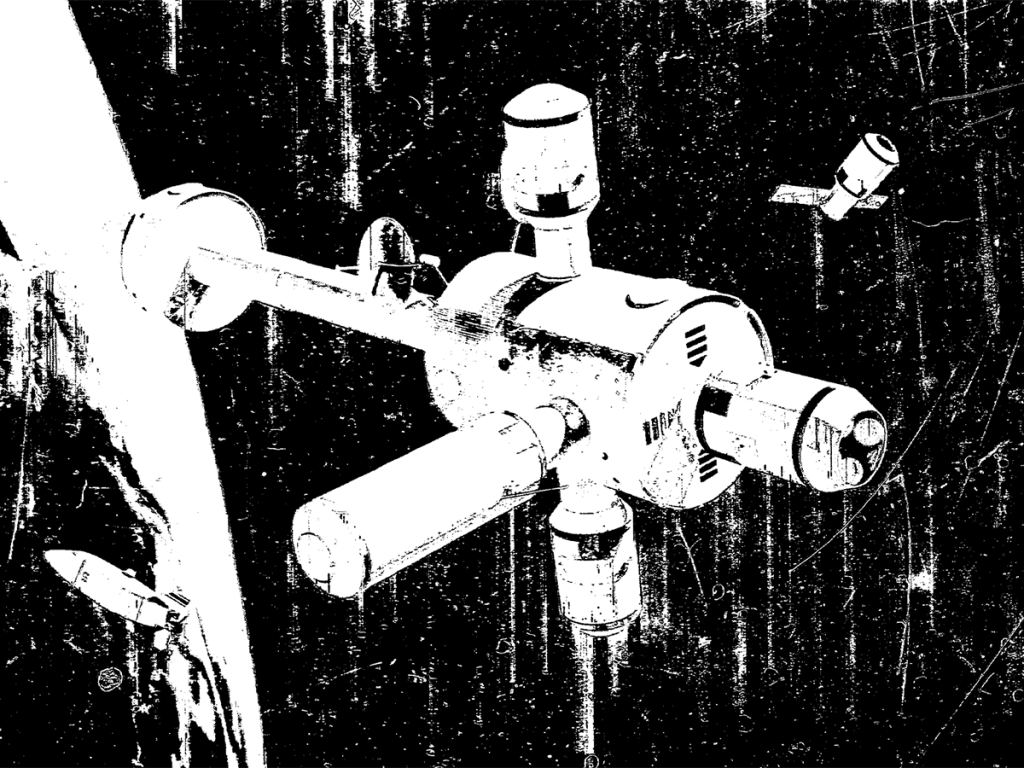
This chart depicts the 12-man Space Station as currently conceived out of the on-going Phase-B Space Station Program Definition activities. The concept shows four decks in the core module, two attached experiment modules, and a detached experiment module floating in the immediate proximity of the Station. The solar arrays represent just one possible means of generating the 25 kilowatts of power required by the Space Station. The core module is 33 feet in diameter and approximately 50 feet in length and is launched by the INT-21 launch vehicle (S-IC/S-II) from one of the Saturn-V launch pads already in existence at Kennedy Space Flight Center. The Space Station is designed to operate in a low earth orbit at an altitude of 200 to 300 nautical miles and a nominal inclination of 55 degrees. Current planning indicates that this Space Station could be launched late in Calendar Year 1977 and could operate for several years in the 1980’s.
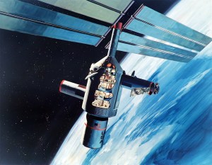
This chart shows an artist’s concept of the 50-man Space Base. The crew modules used in the Space Base can be evolved from the 12-man Space Station module. The concept shows the two nuclear reactors which provide electrical of up to 100 kilowatts, joined to the zero-g hub. The Space Base, which operates in low earth orbit during the decade of the 1980’s, is a multipurpose research and development facility to which scientist and other users can be transported by the Shuttle and which will support these people they are undertaking their particular activities in orbit.
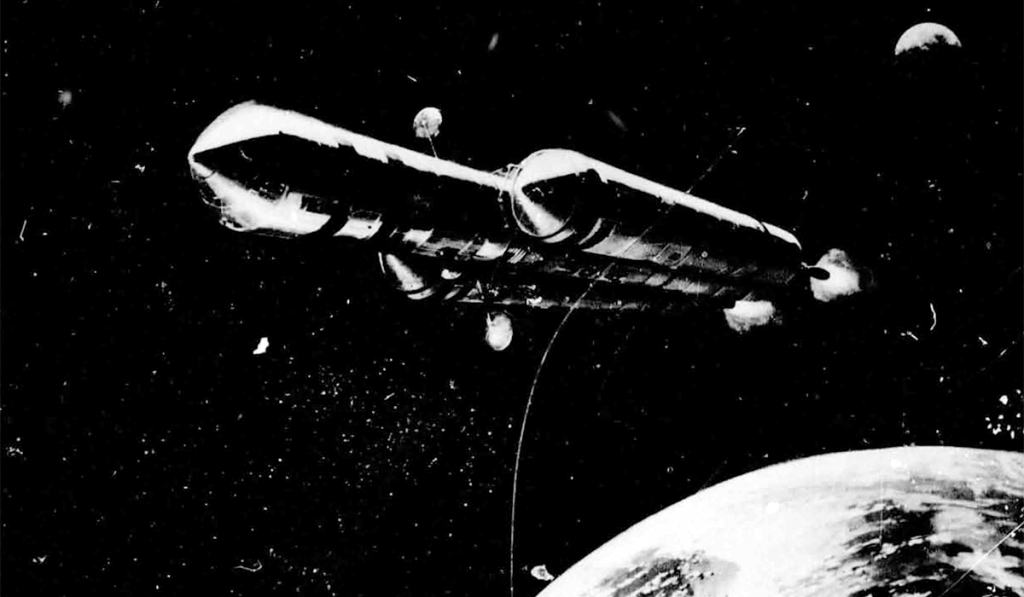
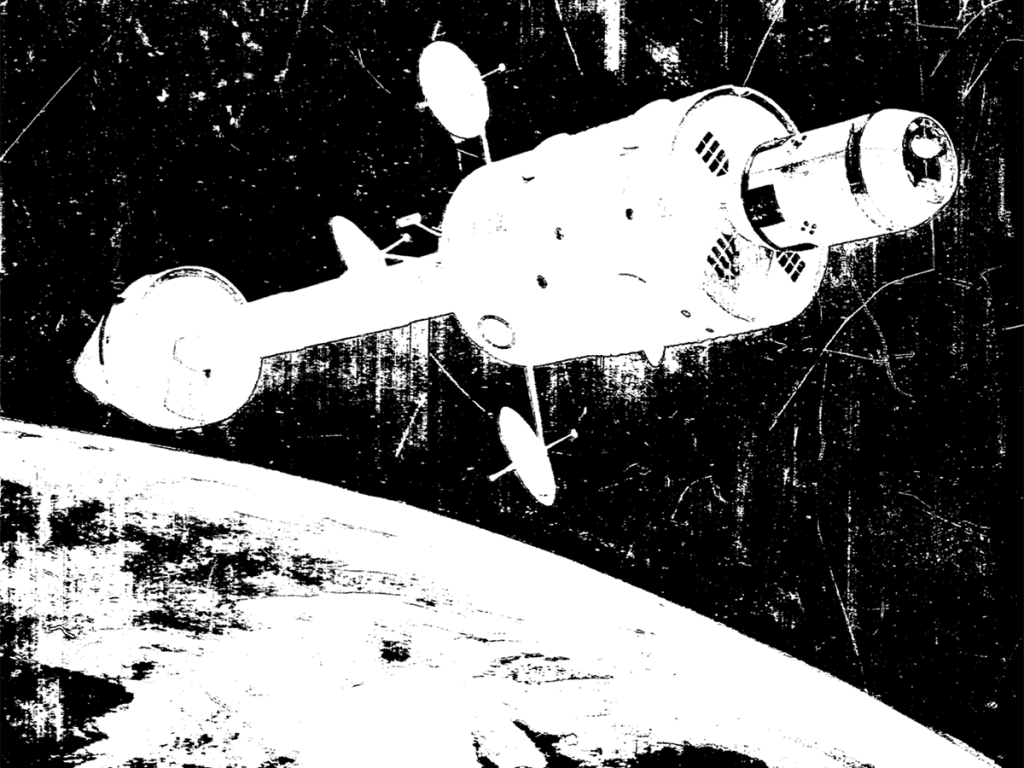
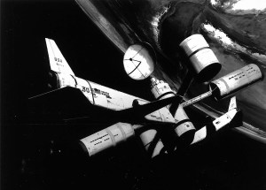
The Phase-B Space Station Program Definition activities have also considered the evolution of the Space Station module into the manned planetary mission module. Shown here is an artist’s concept of the manned planetary vehicle as it leaves the earth on the transplanetary mission in the mid – to the late – 1980’s.
Nuclear propulsion using the Nerva-1 type engines provides the primary propulsion for this deep space mission. The primary mission under consideration is onward which will accomplish a Mars landing using the Mars orbital rendezvous technique and a swing by Venus on the return leg to earth. Depending on the mission opportunity, the total mission duration is between one and two years. The 12-man earth orbital has a large number of the features required by a planetary mission module; and is desirable, where possible, to shape the Space Station program in such a way that it represents the maximum step along the road to this mission of the future, while at the same time it does not compromise the Station for its primary earth-orbit mission objectives.
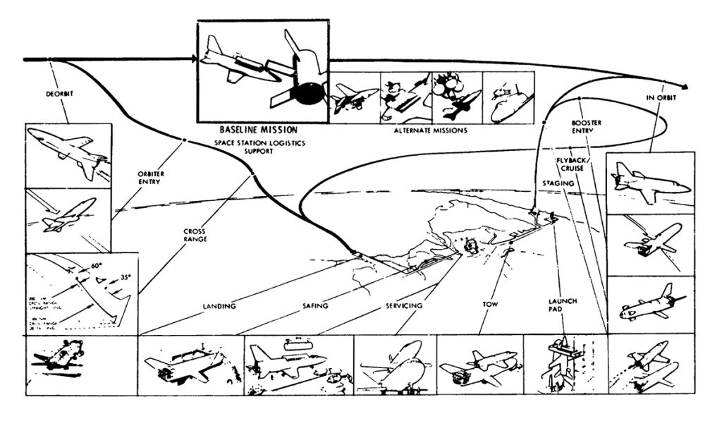
During the late 50’s and the decade of the 60’s, the limitations of technology required that the transport of man and other payloads to earth orbit be accomplished by a multistage expendable launch vehicle. as the level of activities in earth orbit increases and as the number of crew and amount of cargo requirements to be transported to earth-orbit increases, the desire for a much lower cost and more convenient means of transporting personnel and material to orbit is obviously required. The two-stage, all-reusable shuttle depicted here is one means of accomplishing this. Whereas the development of a system like this type requires the dedication of considerable resources over several years, the tremendous increase in convenience and economy represents the essential breakthrough necessary for a viable space program.
Deck 1
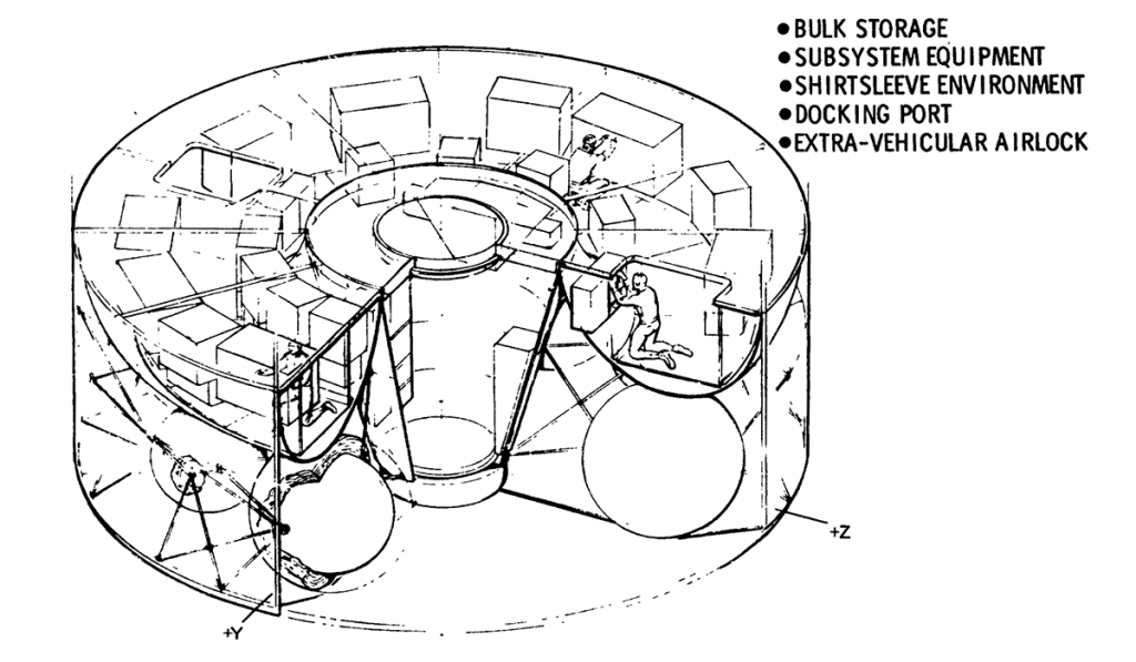
A greater detailed look at the lower torus area/tunnel in addition to the bus storage are shoes the large, extravehicular airlock with the docking port at the outer end. This area is a completely shirt-sleeve environment. A main aisleway is utilized in the torus to allow crewmen access to the equipment mounted on both sides of the aisleway. The aisleway and equipment are structurally supported from the Deck-1 bulkhead above, which forms the ceiling of the toroidal area. Two large 4- by 5- access openings in the Deck-1 bulkhead (toroidal ceiling) provide access to the toroidal area. The lower tunnel is also utilized as an extra-vehicular airlock with a docking port at one end and pressure hatch at the other. Below the torus area are located the propellant tanks of the RCS.
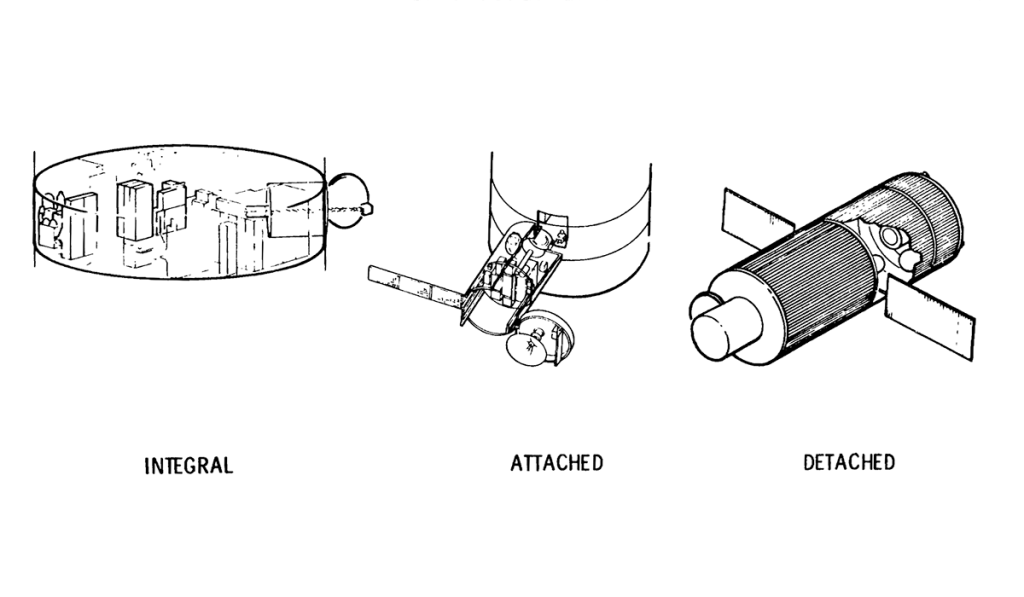
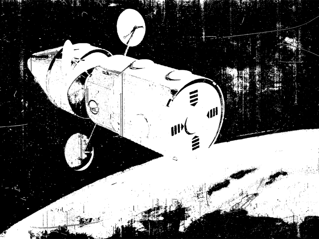
The experiments operating on the Space Station can either be accommodated integrally to the core module in a module that is attached to one of the docking ports on a semipermanent basis but which can be easily be replaced when its usefulness has expired and in detached flying-type modules which periodically rendezvous and dock with the Space Station core module for periodic module and experiment maintenance, update, film/tape reloading, etc.
Presenting a more detailed look at the mission from launch to docking, this chart depicts the launch readiness through the max q and the subsequent staging operations, the insertion into 50 by 100 nautical-mile elliptical orbit, and the subsequent rendezvous and docking maneuvering.
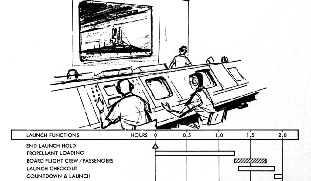
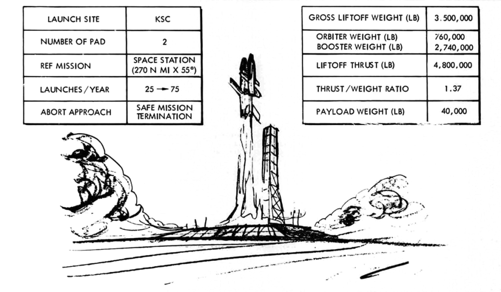
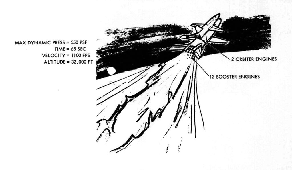
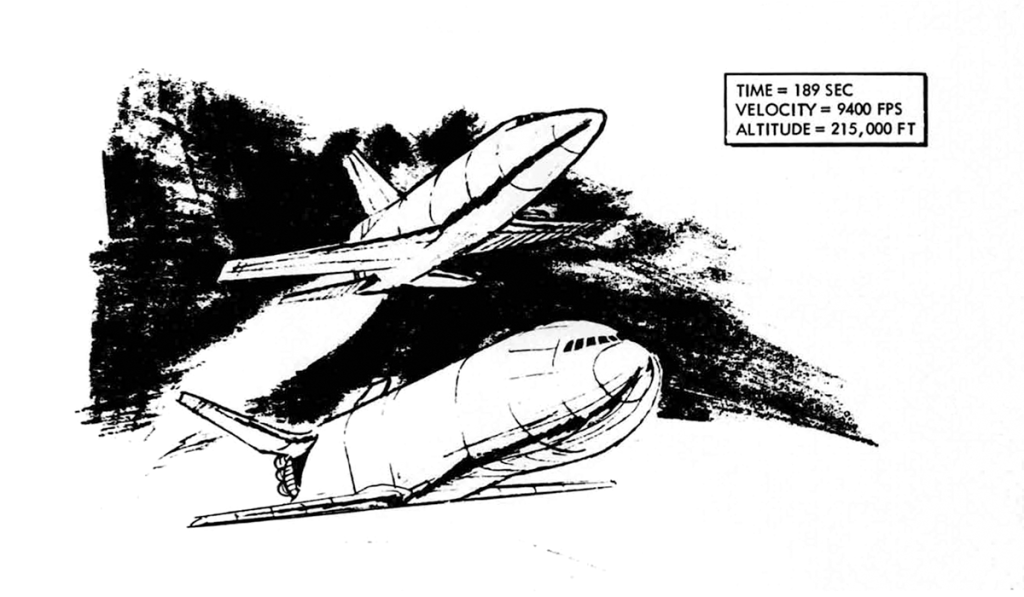
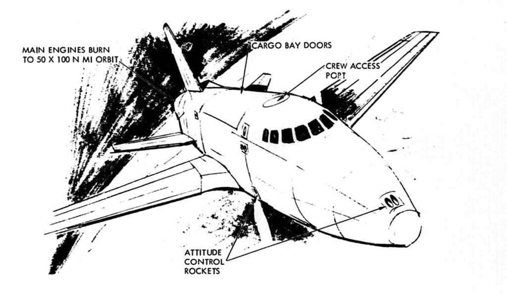
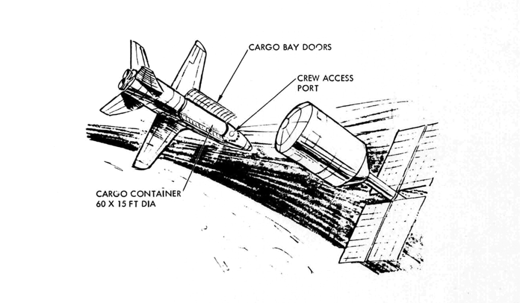
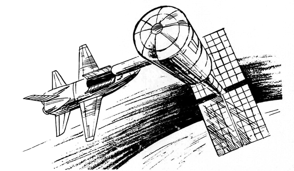
Image credit: North American Rockwell
File source: NASA NTRS
Selected Plates From:
June 3-5 1970
Speaker: C.J. Dorrenbacher – Advance Systems and Technology
McDonnell Douglas Astronautics Company
The launch vehicle places the Space Station into a 456-kilometer circular orbit at an inclination of 55 degrees. The S-II second stage is separated and deorbited into a preselected deep-ocean area. The critical systems – communications, life support, etc. – are activated and the readiness of the Space Station for manned occupancy is verified prior to committing the launch of the logistics system that will carry the Space Station crew.
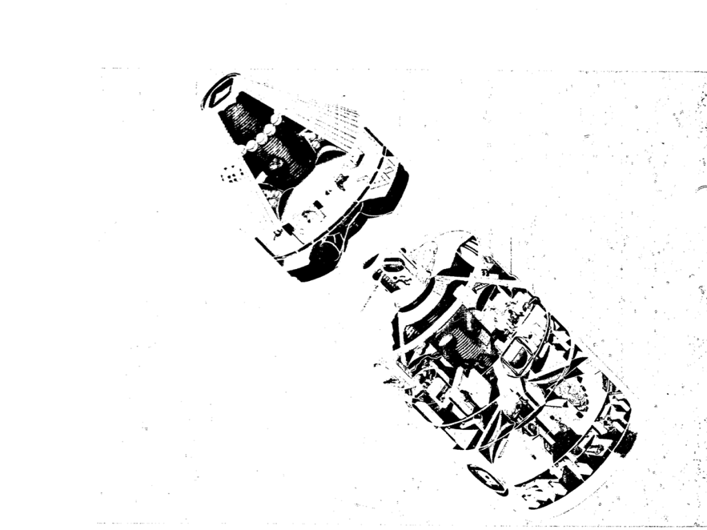
The logistics system, which consists of the logistics spacecraft (or orbiter) and the crew/cargo module is launched 24 hours after the launch of the Space Station. After rendezvous some 8 hours later, the crew/cargo module separates from the logistics spacecraft and propels itself toward a docking maneuver with the Space Station. After docking, the crew enters the station, activates the remaining systems, and advises the orbiter that station operations can begin. Approximately 25 hours after initial manning, the orbiter begins its return flight to Earth.
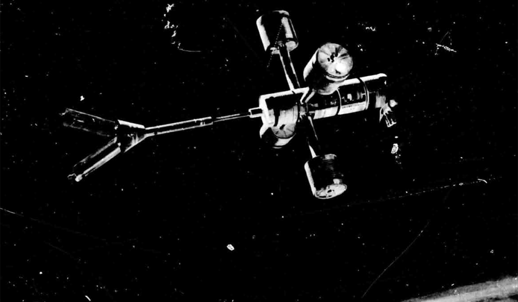
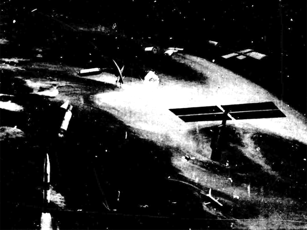
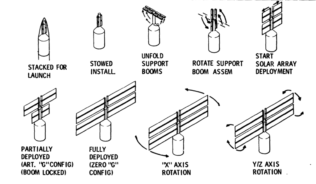
During the first month, the crew activates all systems and readies the station for artificial-gravity test operations. The artificial-gravity module is deployed on a telescoping spoke. The combined mass of the artificial-gravity module and the station is spun around the center of gravity; the resulting centrifugal force produces a simulated gravity environment. The purpose of this operation is to explore the potential benefits and problems associated with artificial gravity.
When the artificial-gravity operations are completed, the logistics system begins delivery of additional experiments contained in modules; typically the Space Station may have three or four modules attached to it while three or four modules are flying free around it. Logistics appointments become regular (nominally. every 90 days) and experiment program is in full swing.
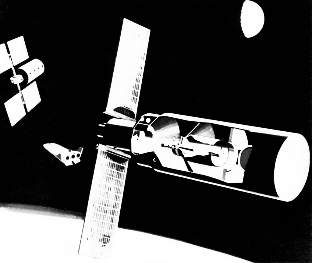
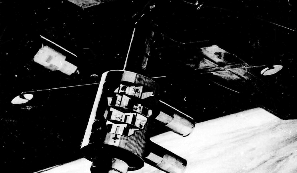
The Space Station is shown in a cutaway perspective. Equipment and activities are depicted as they would look upon completion of the outfitting of the station. The telescoping spoke is abbreviated for the purpose of this illustration.
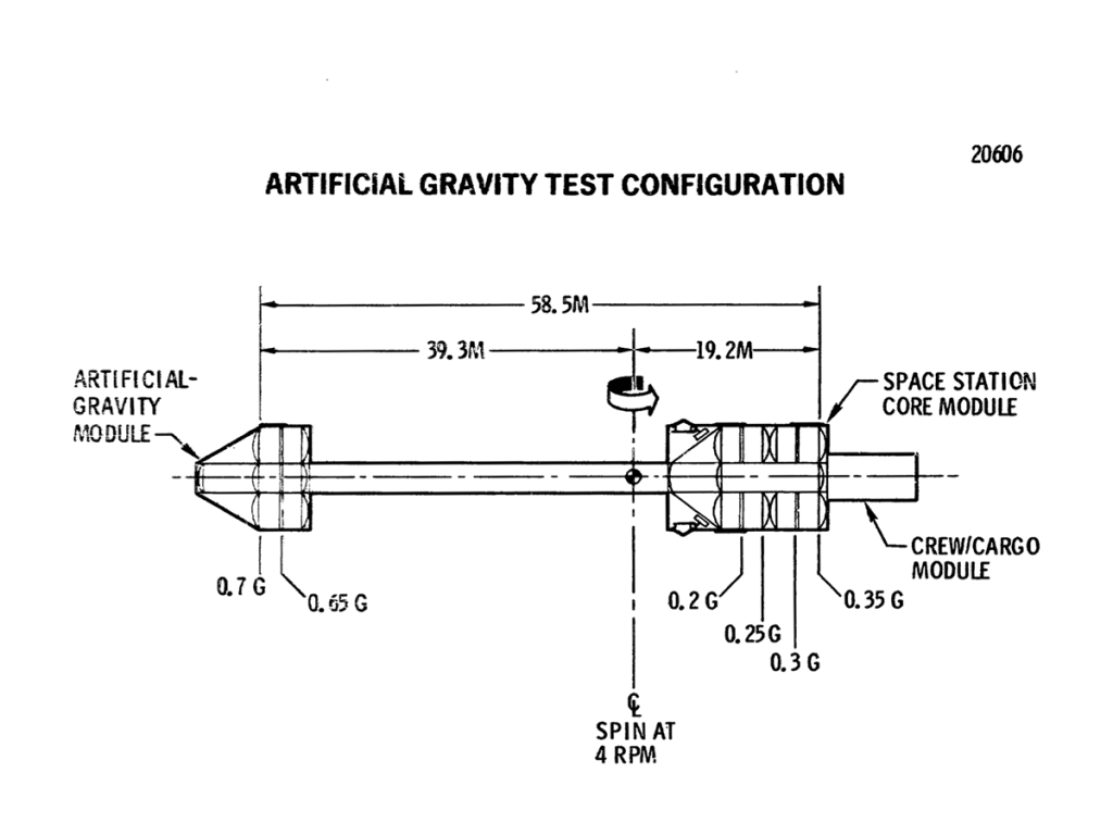
During the 30-day artificial-gravity experiment, half the crew (six-men) occupies the deployed artificial-module. The men will live in the same environment as those remaining in the core module except that their effective gravity will be higher (0.7g) than it is in the core module. Some of the core will inhabit a zero-gravity cab located at the center of rotation; there they will duplicate certain tasks being performed in artificial gravity so the effects of the two enviroments can be compared. Of major interest is an evaluation of the effects of going to a zero-gravity environment to an artificial-gravity environment. The Space Station can repeat the artificial-gravity test as required: about five repetitions are assumed for design purposes.
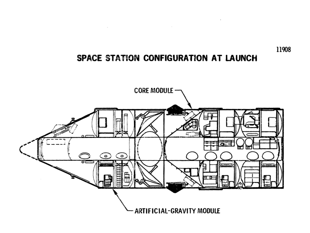
The Space Station is 9.2 meters in diameter and about 34 meters. It consists of a core module. Further modular division is visible in that the core module contains two separate modules, each consisting of two decks; a third two-deck module comprises the habitable portion of the artificial-gravity module.
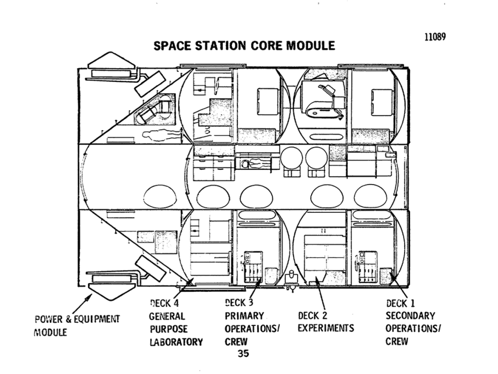
The core module contains three pressurized compartments; the compartment formed by Decks 1 and 2, the compartment formed by Decks 3 and 4, and the central tunnel. This feature ensures that a habitable environment will be available should pressure be terminated in either of the two primary compartments. The tunnel serves as the primary traffic route for men and equipment between the decks. The forward end of the core module contains the isotopes/Brayton electrical power system in an unpressurized environment and a storage compartment, which may be pressurized for access.
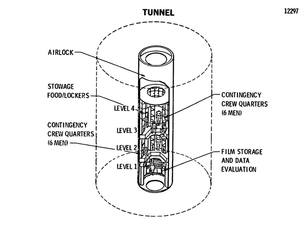
The core module tunnel has many functions other than that of being the main traffic artery. Contingency provisions are available should habitation of this compartment be required.
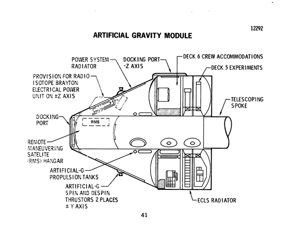
Similar to the forward half of the core module, the artificial-gravity module contains a two-deck module and a conical section containing a propulsion system to provide the spin necessary for artificial-gravity operation. This conical section also has provisions to increase the electrical power capability of the Space Station through the later addition of one or more isotope/Brayton units. Initially, Deck 6 is configured as a crew and operations facility for the artificial-gravity experiment. When the equipment used in the crew and operations facility is stowed, the volume can be converted to accommodate additional research facilities. If the need arise to accommodate a larger crew (up to 18 men), this deck can be reconverted to a crew facility. Two centrifuges occupy Deck 5.
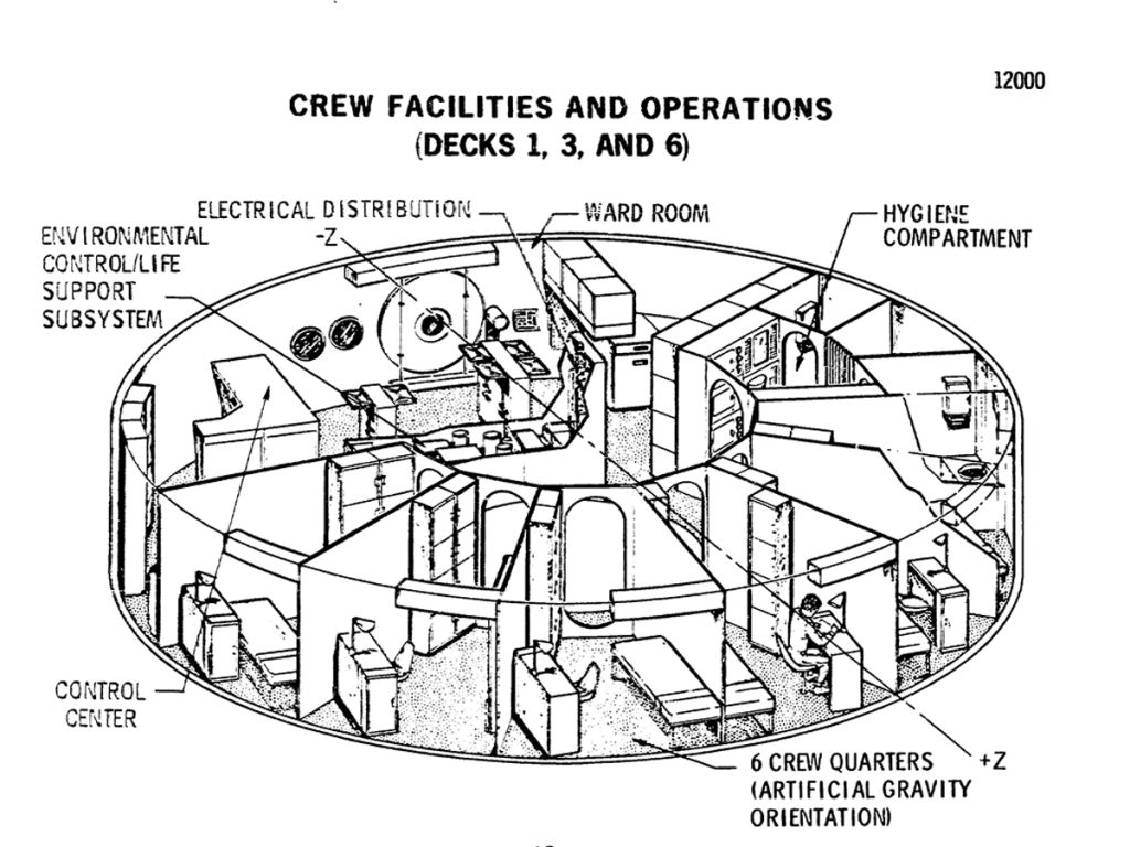
One deck in each of the three modules is configured to support the crew. Facilities on each deck are sized to provide private quarters and eating and hygiene facilities for six men. However, the life support system will accommodate the entire crew of twelve on any deck. The layout is shown for the artificial-gravity module.
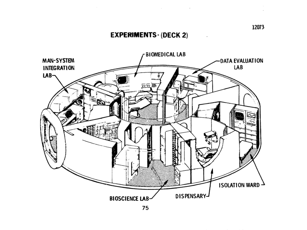
Deck 2 is dedicated to experiment activities associated with the study of various life forms in zero activity. man, animals, plants, micro organisms are all subjects for analysis. Considerations of equipment and facility commonality result in locating the dispensary and isolation ward adjacent to these laboratories.
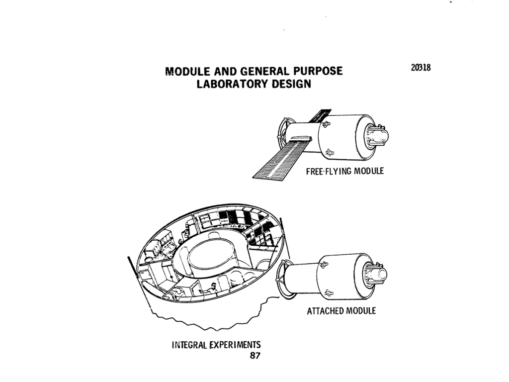
Experiments may be accommodated either within the Space Station or in attached or free flying modules that use services provided by the Space Station. Internal experiments are either launched with the Space Station or brought up layer by the logistics system, transferred aboard, and installed; all attached and free-flying modules are delivered to orbit by the logistics system.
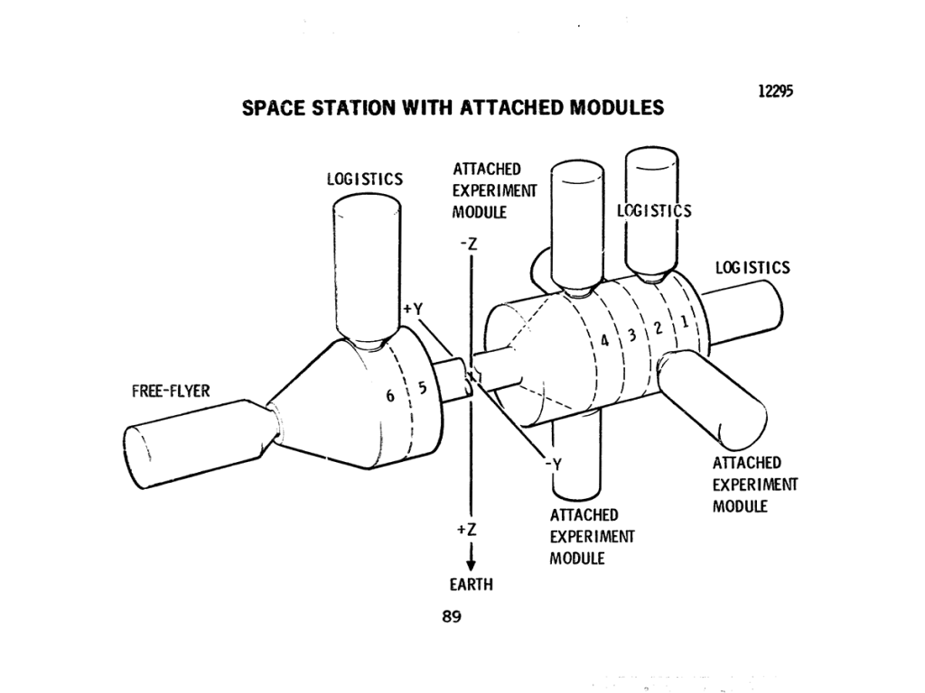
The Space Station contains a total of eight docking ports; these ports are of a universal design to accommodate either crew/cargo modules or attached to free-flying experiment modules. Normally, logistics modules will dock on the artificial gravity module and the aft end of the core module. The free-flying experiment modules will share the forward docking port, while all attached modules dock to the core module.
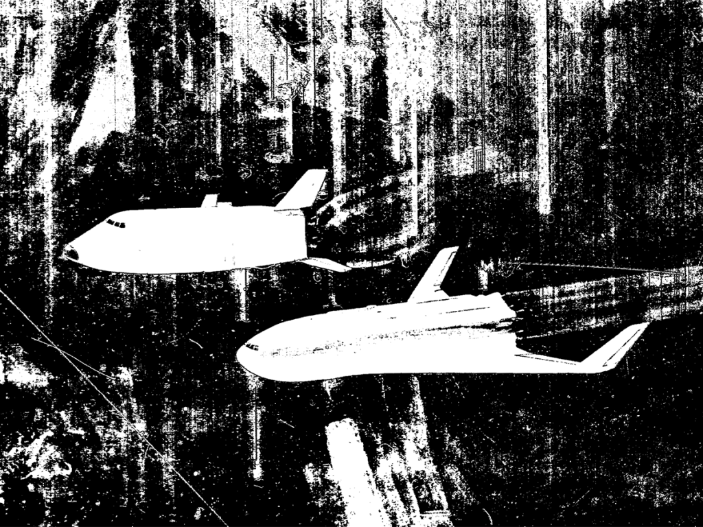
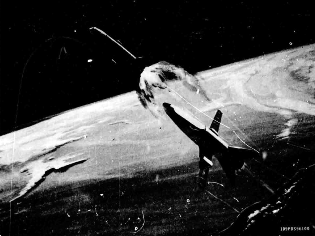
The orbiter is seen separating from the booster stage, which now prepares to return to Earth.
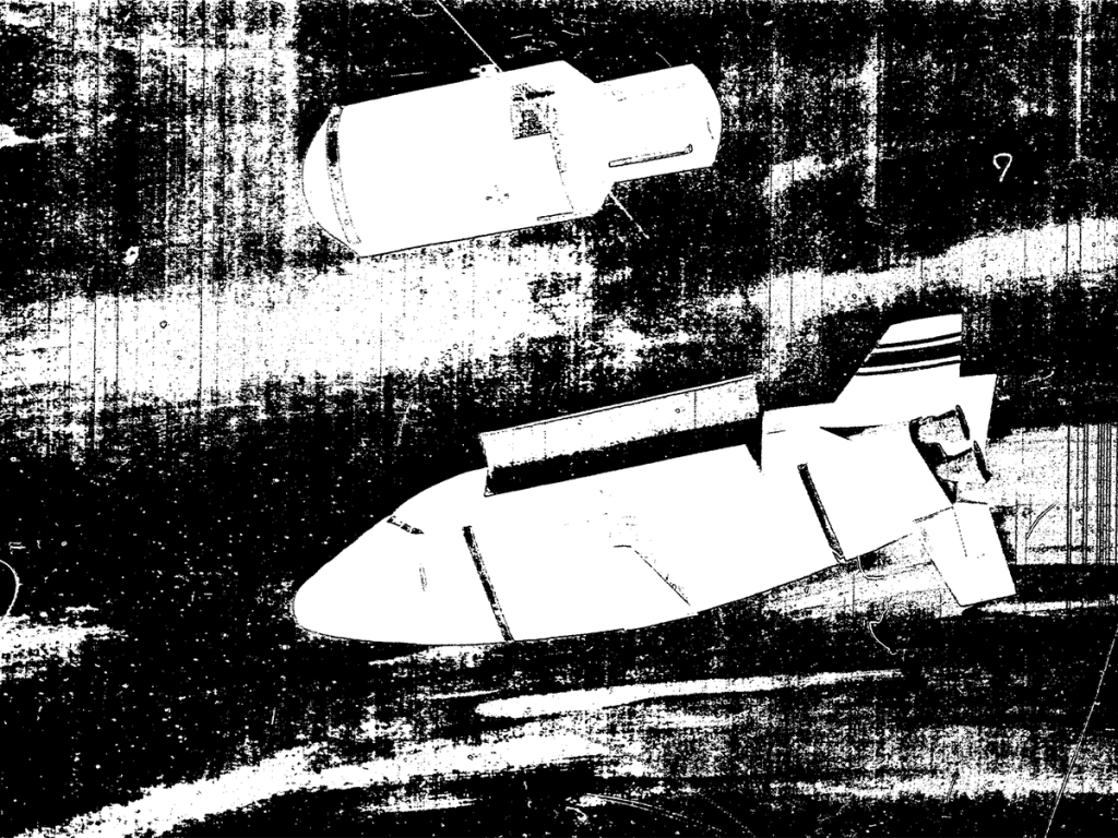
A typical payload for the logistics system is an experiment module leaving the cargo bay. Its propulsion system has ignited as it makes its guided way to the station.
Image credit: McDonnell Douglas
Image source: NASA NTRS
Third release week of November 15, 1971
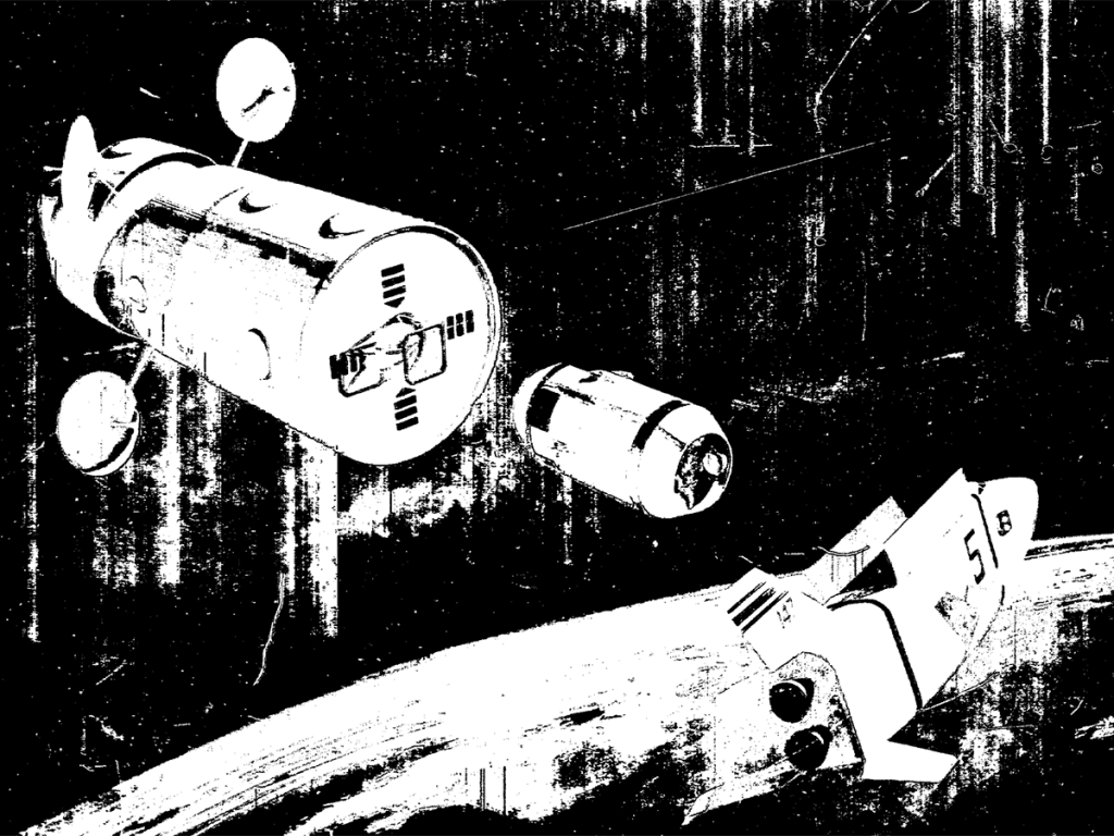
THE 6:10 INTO SPACE. NASA is working on the design of a winged shuttle craft to resupply the manned space stations of the next decade. The giant space transports shown here can carry 50,000 pounds of men and cargo to the cluster of cylinders that make up a space base, the return to Earth and land like airplanes.
Credit: North American Rockwell
Image credit: North American Rockwell
Image source: Numbers Station
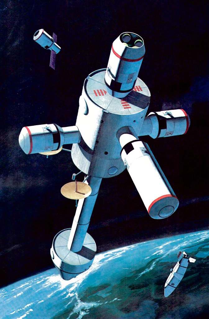
Image credit: McDonnell Douglas
Image source: Numbers Station
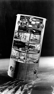
Image credit: North American Rockwell
Image source: Drew Granston
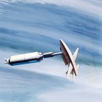
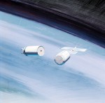
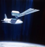
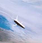
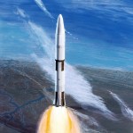
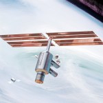
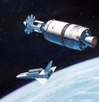
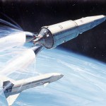
Image credit: North American Rockwell
Image source: Numbers Station
