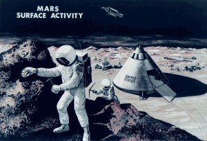
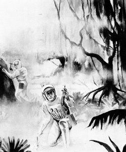
Extraterrestrial explorers, in space suits, gather samples from strange planet, to determine its adaptability to supporting human life.
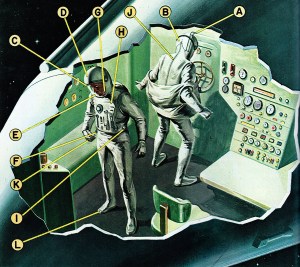
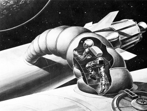
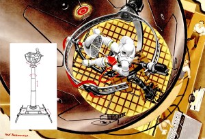
SPACE SUIT SYSTEMS – While space suits are unnecessary within the spaceship, they are vital for activities outside the vessel, or on asteroids or planets. (A) direct audio communications aerial; (B)(J) receiving aerial (also serves as suit zipper); (C) unbreakable glass visor; (D) helmet visor to be lowered against strong light or radiation; (E) voice diaphragm; (F) electric systems; (G) microphone; (H) tools and suit controls (heat, etc.) (I) nitrogen inflation nozzle; (K) flexible metal gloves; (L) magnetic and heated shoes.
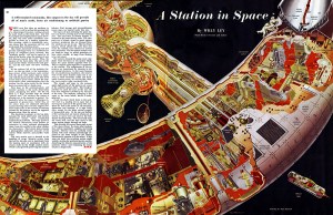
DIRECT RADITATION SYSTEM – Useful for relatively longer mission durations such as one or two months. This could be a lunar observation or space laboratory type mission. Because of the weight penalty resulting in the need to store a large quantity of expendable liquid such a system can no longer be considered for mission durations exceeding one or two weeks. Where the storage of relatively larger food quantities is required, a satisfactory system would be one in which heat is conducted away from the food to a fin providing a large surface area for direct radiation of the heat to space. Such a system would operate best if the radiating surfaces were to face away from the sun. The fin is therefore shown attached to a solar collector (part of another system) which is maintained in an orientation always facing the sun. The large radiator surfaces will then face away from the sun. The food stored by such a system would again be provided in special containers to permit eating in the absence of gravity. Special provisions such as suction cups on the food containers permit the astronaut to stand the food containers on table or shelf. Magnetic shoes permit him to walk about the cabin in the usual manner.
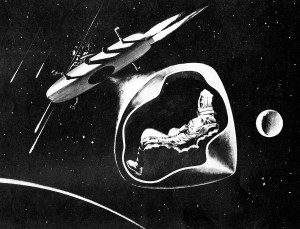
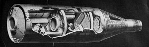
Space escape capsule. After escape from damaged ship, rescue is possible from this “lifeboat’ of space.
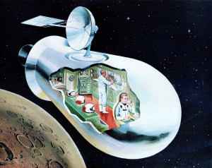
Transferring from shuttle ship to space ship in orbit. Larger ships need not land on moon or planet.
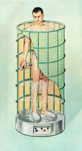
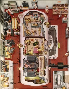
NEEDLE SPRAY BATH SYSTEM – Water on long missions must be closed-system, used over and over for all purposes. Waste water collected from all sources, redistilled and purified is shown here being used for a full bath. Heat is procured from the solar collector, is removed via the distillation process, and in turn converted into electricity to run the motors controlling the needle sprays on circulating system. Degradable detergents are used instead of soap, and recovered for reuse in the distillation process.
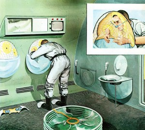
WASHROOM AND TOILET SYSTEMS – Hand and face are miniature needle spray systems, used for ablutions and for face rinse after shaving. Toilet facilities operate on air-suction principle, and all water is removed from wastes and purified for re-use in the entire bathroom system.
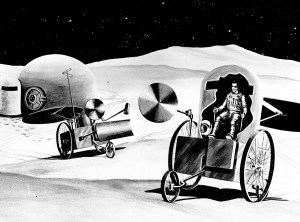
Manned lunar roving vehicle, capable of maneuvering about the airless desert landscape.