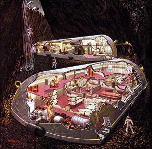
More about Man on the Moon
Collier’s, October 25, 1952
Image credit: Collier’s
Image source: AIAA Houston
More about Man on the Moon
Collier’s, October 25, 1952
Image credit: Collier’s
Image source: AIAA Houston
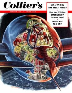
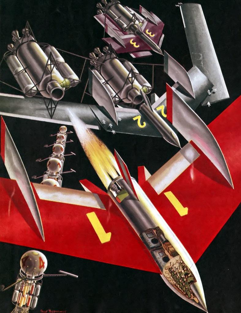
How Man will Meet Emergency in Space Travel
Collier’s, March 14, 1953
Image credit: Collier’s
Image source: AIAA Houston
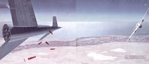
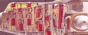
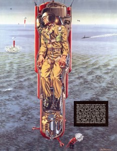
Before space-going rocket tries out its power, it will undergo tow tests behind jet bomber. Crew will board it, try emergency procedures–including bail-out, shown above.
How Man will Meet Emergency in Space Travel
Collier’s, March 14, 1953
Image credit: Collier’s
Image source: AIAA Houston
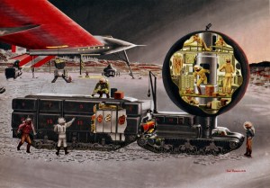
Is there Life on Mars?
Collier’s, April 30, 1954
Image credit: Collier’s
Image source: AIAA Houston
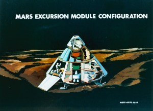
Image credit: NASA Lewis
Image source: National Archives
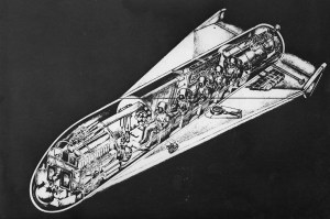
This is a Martin Co. engineering design of a shuttle vehicle to carry five men, or an equivalent amount of equipment, to a rendezvous in orbit with a space station. After delivering it’s load, this vehicle returns to earth by following a glide pattern and slowing in the earth’s atmosphere until landing speed can be attained.
Image credit: Martin
Image source: Numbers Station
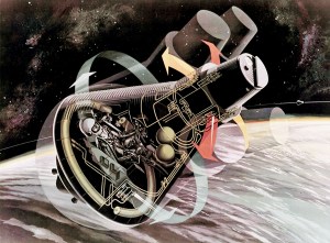
Image credit: NASA
Image source: NM Space Museum
Image credit: NASA JSC
Image source: NASA Images
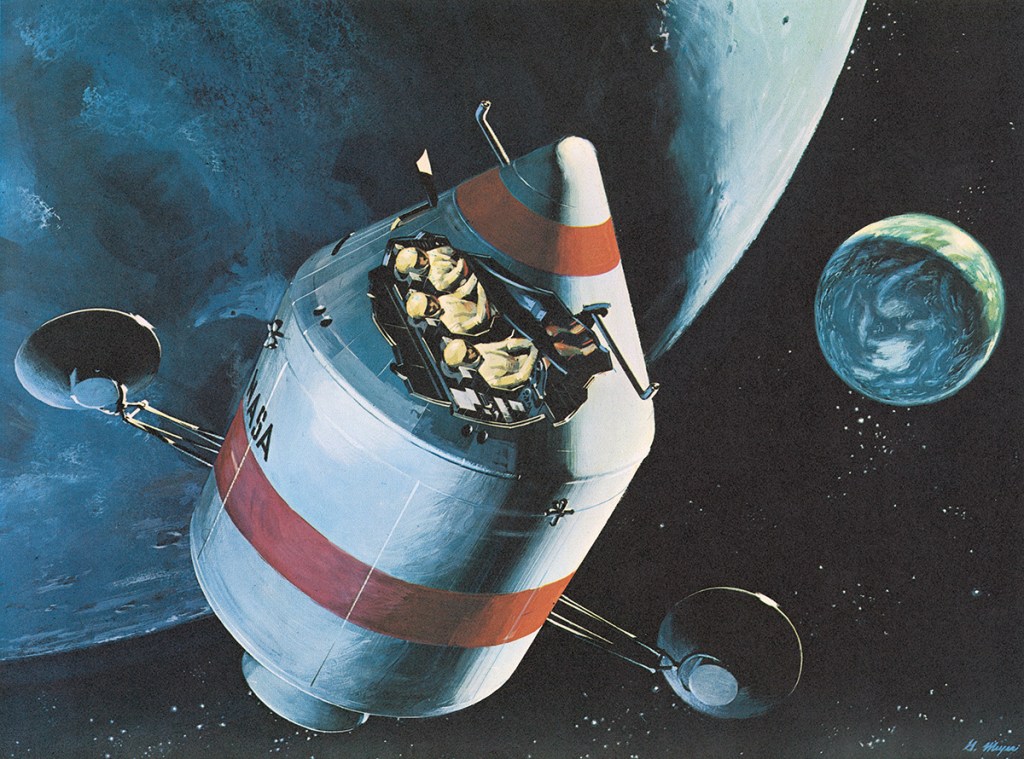
Image credit: North American Aviation
Image source: Numbers Station
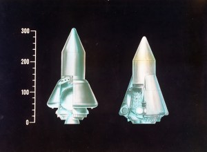
Image credit: Convair
Image source: SDASM Archives
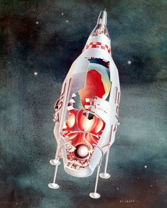
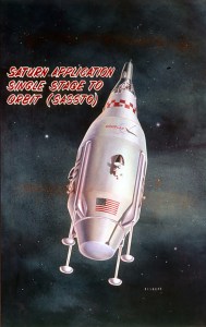
SASSTO (Saturn Application Single-Stage-to-Orbit) combined launch vehicle and spacecraft. Only 62.3 ft (19m.) tall, a single plug-nozzle engine would serve both as launch vehicle and for soft-landing back on Earth after an orbital mission. The craft – seen here with a Gemini two-man capsule – would be recovered intact and could be used repeatedly. It would be a particularly appropriate for ferry missions into Earth-orbit including the emergency rescue of astronauts.
Image credit: Douglas
Images: SDASM Archives

B&W (As seen in Roundup dated Nov. 24, 1967)
NOV. 67 S-67-51373
MANNED SPACE CENTER, HOUSTON, TEXAS
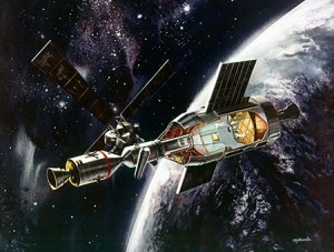
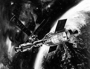
ORBITAL WORKSHOP — Artist’s concept showing how a Saturn S-IVB stage will appear when converted to the Apollo Applications Orbital Workshop. Launched fully fueled with airlock and docking adaptor attached, the S-IVB’s liquid hydrogen tank becomes a shirtsleeve environment workshop after the fuel has been depleted. At left is an Apollo Command and Service Module launched separately and docked into one of the docking adaptor’s ports. The Apollo Telescope Mount is shown docked into one of the side ports. The ATM will be joined to the cluster in a second phase of the program. Solar cell “wings” to provide power fold outward from the S-IVB after orbit is achieved. McDonnell Douglas Corporation’s Missile and Space Systems Division is making the S-IVB orbital workshop modifications under contract to NASA Marshall Space Flight Center and McDonnell Astronautics Company is developing the airlock under contract to MSC. (MCDONNELL DOUGLAS PHOTOGRAPH)
Look closely and you’ll notice subtle differences between this version of the painting and a colour rendering found in the SDASM Archives I’ve shared before.
If you’re interested in seeing more of Jacobe’s work, his artwork for the Douglas MOL can be found here. The images are small and plastered with watermarks, so it’s a bit of a tease but they are beautiful.
Image credit: NASA
Image source: Numbers Station
