Image credit: NASA MSFC
Image source: NASA Images
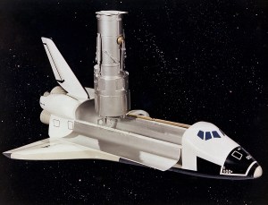
This is an artist’s concept of the Hubble Space Telescope (HST). The HST is the product of a partnership between NASA, European Space Agency Contractors, and the international community of astronomers. It is named after Edwin P. Hubble, an American Astronomer who discovered the expanding nature of the universe and was the first to realize the true nature of galaxies. The purpose of the HST, the most complex and sensitive optical telescope ever made, is to study the cosmos from a low-Earth orbit. By placing the telescope in space, astronomers are able to collect data that is free of the Earth’s atmosphere. The HST detects objects 25 times fainter than the dimmest objects seen from Earth and provides astronomers with an observable universe 250 times larger than is visible from ground-based telescopes, perhaps as far away as 14 billion light-years. The HST views galaxies, stars, planets, comets, possibly other solar systems, and even unusual phenomena such as quasars, with 10 times the clarity of ground-based telescopes. The major elements of the HST are the Optical Telescope Assembly (OTA), the Support System Module (SSM), and the Scientific Instruments (SI). The HST is approximately the size of a railroad car, with two cylinders joined together and wrapped in a silvery reflective heat shield blanket. Wing-like solar arrays extend horizontally from each side of these cylinders, and dish-shaped anternas extend above and below the body of the telescope. The HST was deployed from the Space Shuttle Discovery (STS-31 mission) into Earth orbit in April 1990. The Marshall Space Flight Center had responsibility for design, development, and construction of the HST. The Perkin-Elmer Corporation, in Danbury, Connecticut, developed the optical system and guidance sensors. The Lockheed Missile and Space Company of Sunnyvale, California produced the protective outer shroud and spacecraft systems, and assembled and tested the finished telescope.
Image credit: NASA MSFC
Image source: NASA Images
Selected Plates From:
June 3 Thru 5, 1970
Space Divison
North American Rockwell
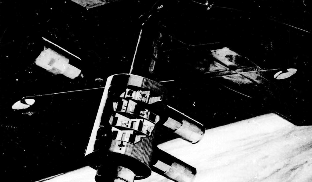
This chart depicts the 12-man Space Station as currently conceived out of the on-going Phase-B Space Station Program Definition activities. The concept shows four decks in the core module, two attached experiment modules, and a detached experiment module floating in the immediate proximity of the Station. The solar arrays represent just one possible means of generating the 25 kilowatts of power required by the Space Station. The core module is 33 feet in diameter and approximately 50 feet in length and is launched by the INT-21 launch vehicle (S-IC/S-II) from one of the Saturn-V launch pads already in existence at Kennedy Space Flight Center. The Space Station is designed to operate in a low earth orbit at an altitude of 200 to 300 nautical miles and a nominal inclination of 55 degrees. Current planning indicates that this Space Station could be launched late in Calendar Year 1977 and could operate for several years in the 1980’s.
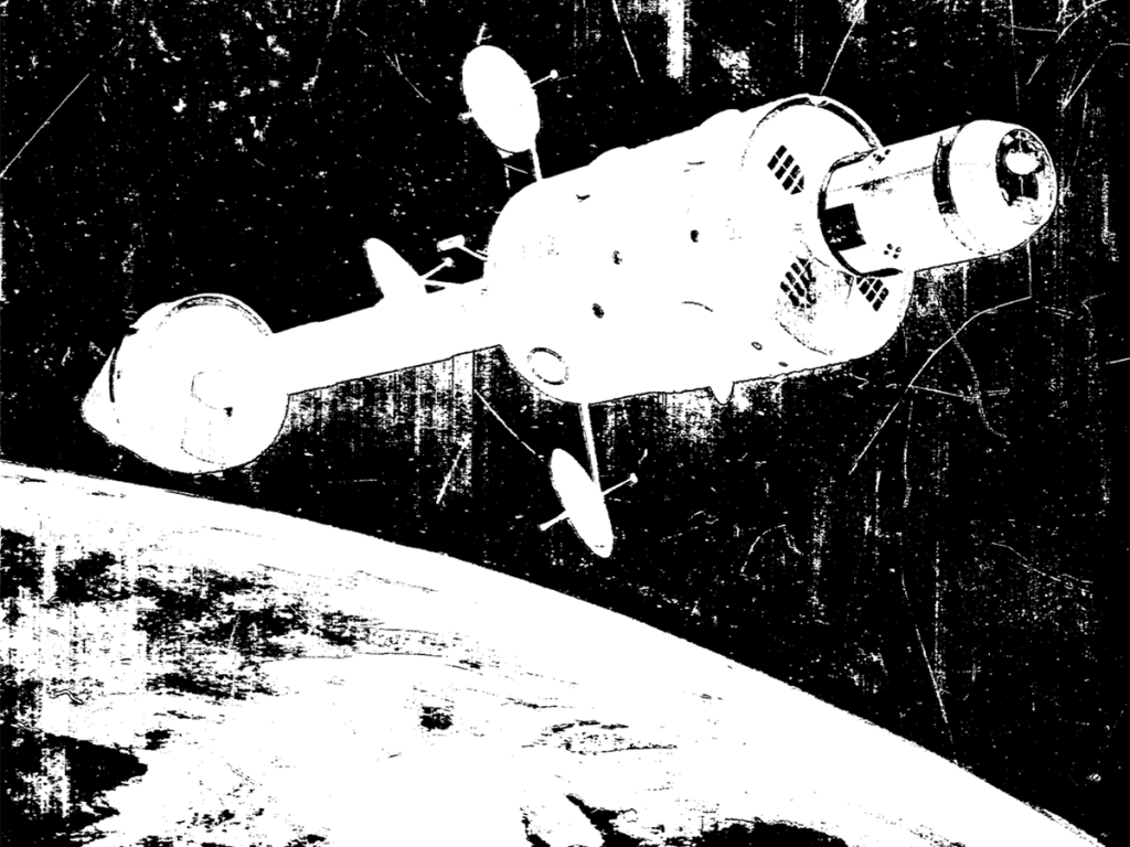
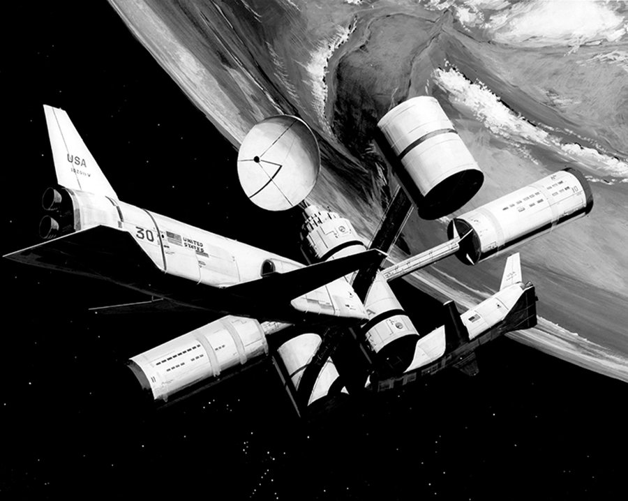
This chart shows an artist’s concept of the 50-man Space Base. The crew modules used in the Space Base can be evolved from the 12-man Space Station module. The concept shows the two nuclear reactors which provide electrical of up to 100 kilowatts, joined to the zero-g hub. The Space Base, which operates in low earth orbit during the decade of the 1980’s, is a multipurpose research and development facility to which scientist and other users can be transported by the Shuttle and which will support these people they are undertaking their particular activities in orbit.
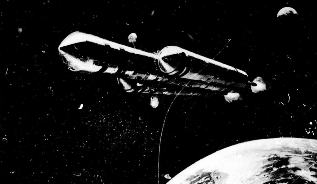
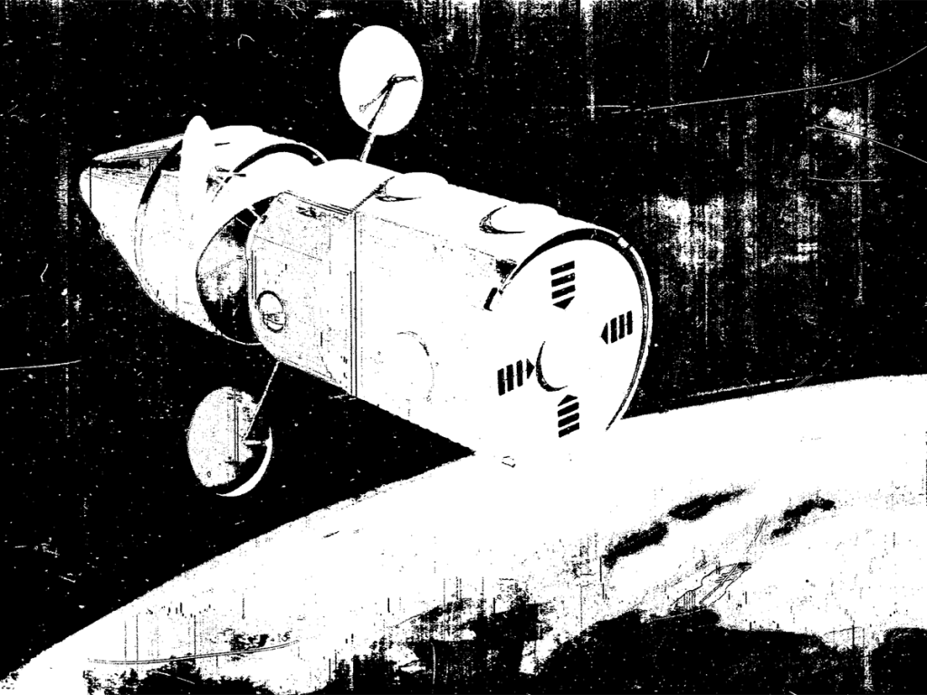
The Phase-B Space Station Program Definition activities have also considered the evolution of the Space Station module into the manned planetary mission module. Shown here is an artist’s concept of the manned planetary vehicle as it leaves the earth on the transplanetary mission in the mid – to the late – 1980’s.
Nuclear propulsion using the Nerva-1 type engines provides the primary propulsion for this deep space mission. The primary mission under consideration is onward which will accomplish a Mars landing using the Mars orbital rendezvous technique and a swing by Venus on the return leg to earth. Depending on the mission opportunity, the total mission duration is between one and two years. The 12-man earth orbital has a large number of the features required by a planetary mission module; and is desirable, where possible, to shape the Space Station program in such a way that it represents the maximum step along the road to this mission of the future, while at the same time it does not compromise the Station for its primary earth-orbit mission objectives.
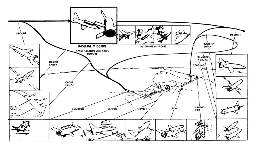
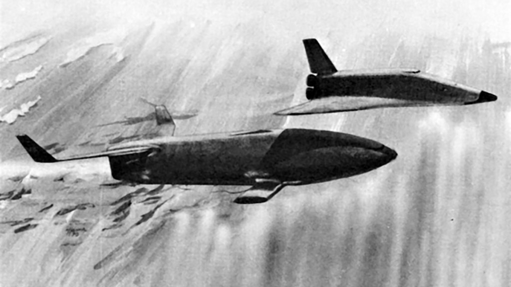
During the late 50’s and the decade of the 60’s, the limitations of technology required that the transport of man and other payloads to earth orbit be accomplished by a multistage expendable launch vehicle. as the level of activities in earth orbit increases and as the number of crew and amount of cargo requirements to be transported to earth-orbit increases, the desire for a much lower cost and more convenient means of transporting personnel and material to orbit is obviously required. The two-stage, all-reusable shuttle depicted here is one means of accomplishing this. Whereas the development of a system like this type requires the dedication of considerable resources over several years, the tremendous increase in convenience and economy represents the essential breakthrough necessary for a viable space program.
Deck 1
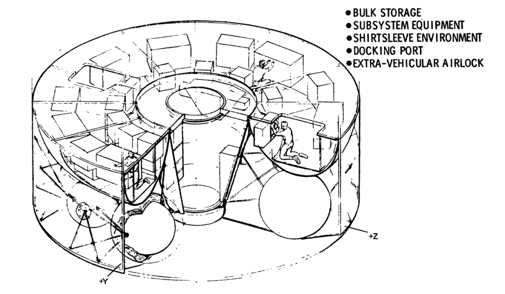
A greater detailed look at the lower torus area/tunnel in addition to the bus storage are shoes the large, extravehicular airlock with the docking port at the outer end. This area is a completely shirt-sleeve environment. A main aisleway is utilized in the torus to allow crewmen access to the equipment mounted on both sides of the aisleway. The aisleway and equipment are structurally supported from the Deck-1 bulkhead above, which forms the ceiling of the toroidal area. Two large 4- by 5- access openings in the Deck-1 bulkhead (toroidal ceiling) provide access to the toroidal area. The lower tunnel is also utilized as an extra-vehicular airlock with a docking port at one end and pressure hatch at the other. Below the torus area are located the propellant tanks of the RCS.
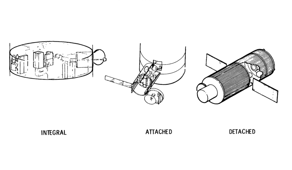
The experiments operating on the Space Station can either be accommodated integrally to the core module in a module that is attached to one of the docking ports on a semipermanent basis but which can be easily be replaced when its usefulness has expired and in detached flying-type modules which periodically rendezvous and dock with the Space Station core module for periodic module and experiment maintenance, update, film/tape reloading, etc.
Presenting a more detailed look at the mission from launch to docking, this chart depicts the launch readiness through the max q and the subsequent staging operations, the insertion into 50 by 100 nautical-mile elliptical orbit, and the subsequent rendezvous and docking maneuvering.
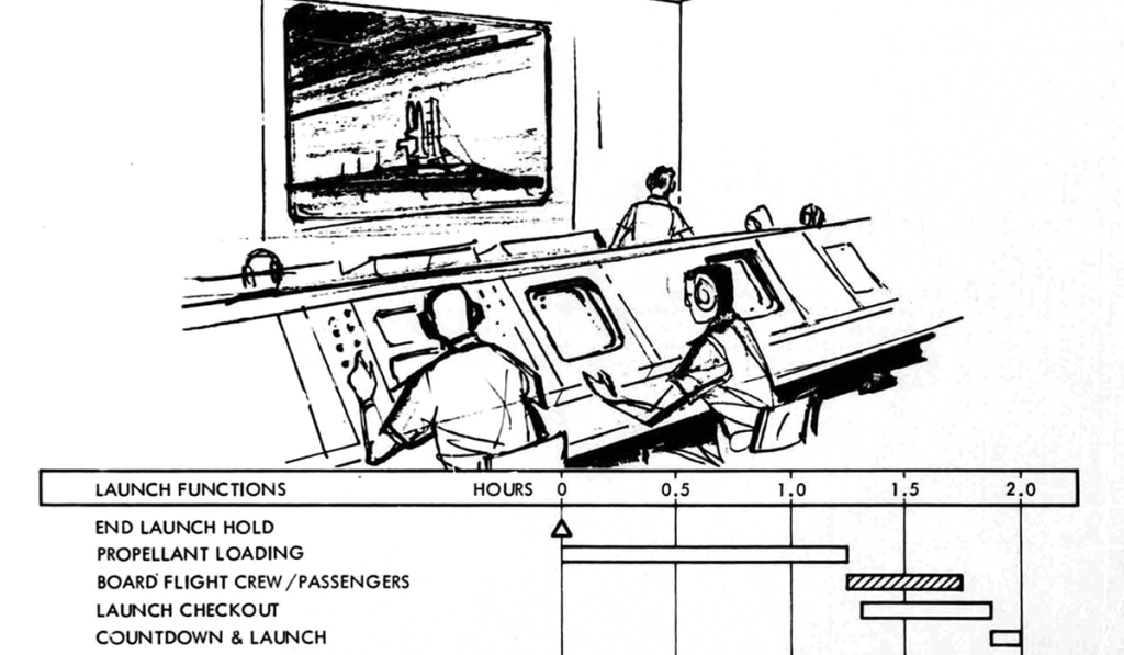
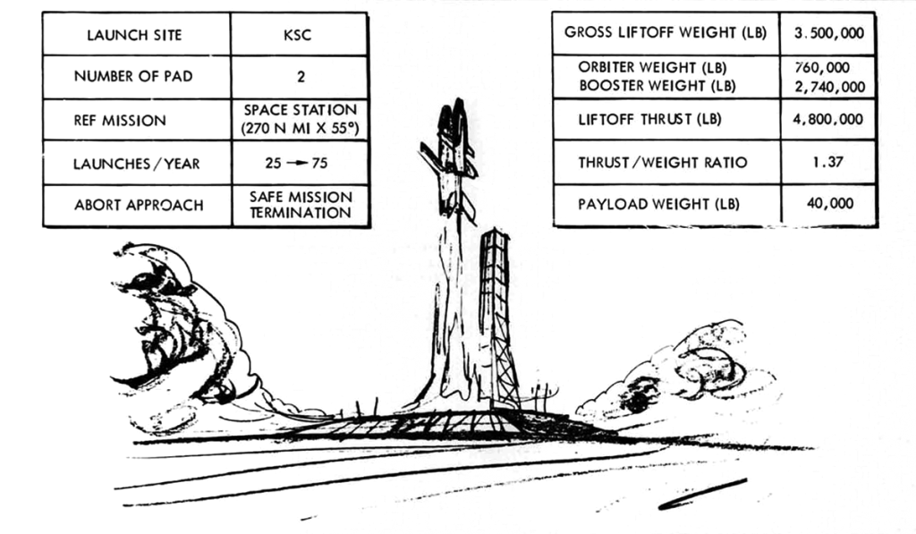
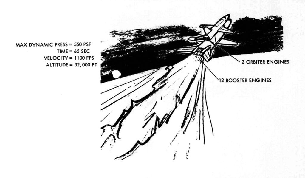
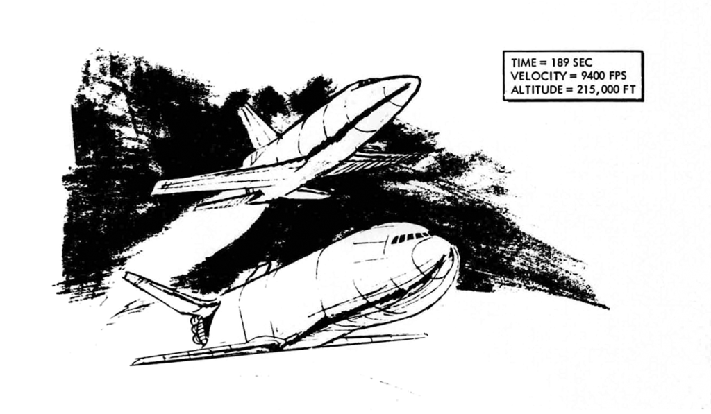
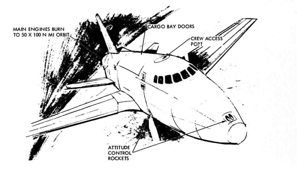
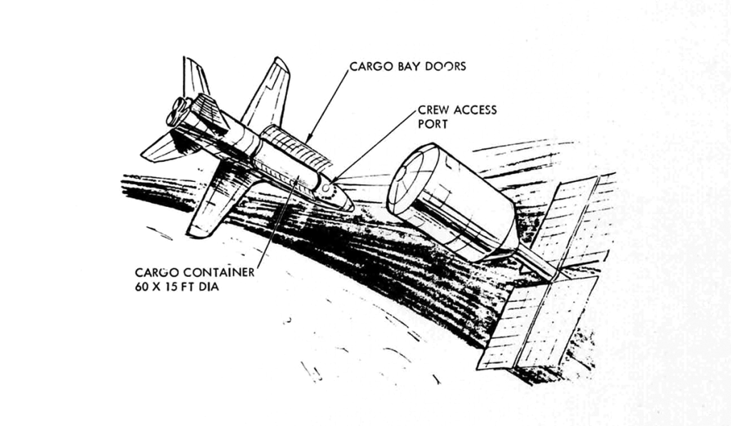
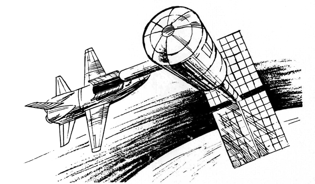
Image credit: North American Rockwell
File source: NASA NTRS
Selected Plates From:
June 3-5 1970
Speaker: C.J. Dorrenbacher – Advance Systems and Technology
McDonnell Douglas Astronautics Company
The launch vehicle places the Space Station into a 456-kilometer circular orbit at an inclination of 55 degrees. The S-II second stage is separated and deorbited into a preselected deep-ocean area. The critical systems – communications, life support, etc. – are activated and the readiness of the Space Station for manned occupancy is verified prior to committing the launch of the logistics system that will carry the Space Station crew.
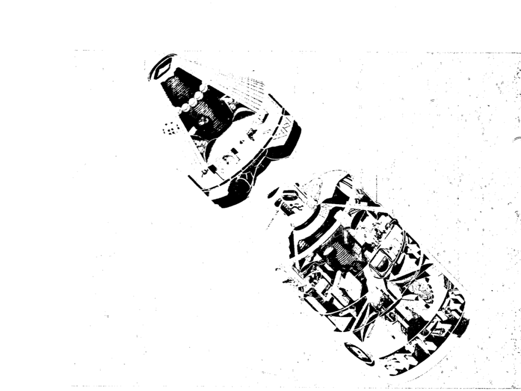
The logistics system, which consists of the logistics spacecraft (or orbiter) and the crew/cargo module is launched 24 hours after the launch of the Space Station. After rendezvous some 8 hours later, the crew/cargo module separates from the logistics spacecraft and propels itself toward a docking maneuver with the Space Station. After docking, the crew enters the station, activates the remaining systems, and advises the orbiter that station operations can begin. Approximately 25 hours after initial manning, the orbiter begins its return flight to Earth.
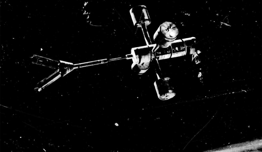
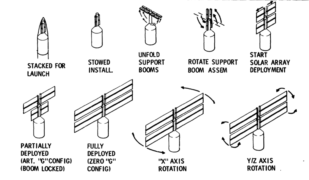
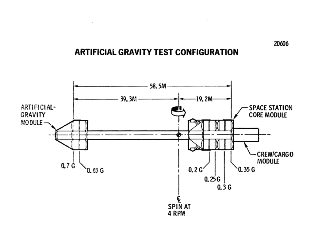
During the first month, the crew activates all systems and readies the station for artificial-gravity test operations. The artificial-gravity module is deployed on a telescoping spoke. The combined mass of the artificial-gravity module and the station is spun around the center of gravity; the resulting centrifugal force produces a simulated gravity environment. The purpose of this operation is to explore the potential benefits and problems associated with artificial gravity.
When the artificial-gravity operations are completed, the logistics system begins delivery of additional experiments contained in modules; typically the Space Station may have three or four modules attached to it while three or four modules are flying free around it. Logistics appointments become regular (nominally. every 90 days) and experiment program is in full swing.
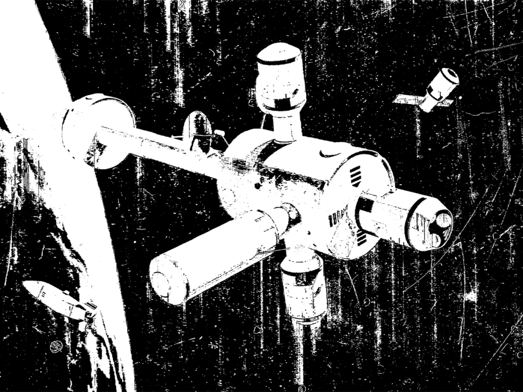
The Space Station is shown in a cutaway perspective. Equipment and activities are depicted as they would look upon completion of the outfitting of the station. The telescoping spoke is abbreviated for the purpose of this illustration.
During the 30-day artificial-gravity experiment, half the crew (six-men) occupies the deployed artificial-module. The men will live in the same environment as those remaining in the core module except that their effective gravity will be higher (0.7g) than it is in the core module. Some of the core will inhabit a zero-gravity cab located at the center of rotation; there they will duplicate certain tasks being performed in artificial gravity so the effects of the two enviroments can be compared. Of major interest is an evaluation of the effects of going to a zero-gravity environment to an artificial-gravity environment. The Space Station can repeat the artificial-gravity test as required: about five repetitions are assumed for design purposes.
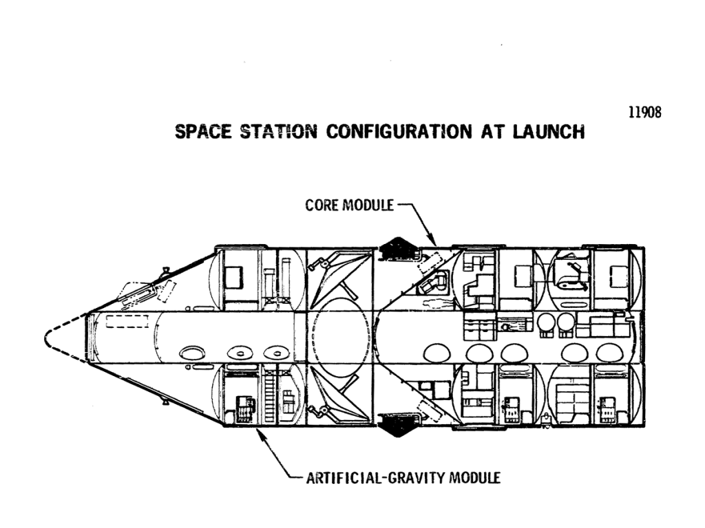
The Space Station is 9.2 meters in diameter and about 34 meters. It consists of a core module. Further modular division is visible in that the core module contains two separate modules, each consisting of two decks; a third two-deck module comprises the habitable portion of the artificial-gravity module.
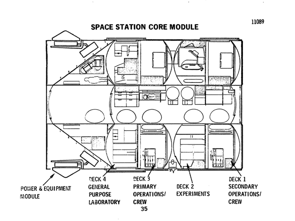
The core module contains three pressurized compartments; the compartment formed by Decks 1 and 2, the compartment formed by Decks 3 and 4, and the central tunnel. This feature ensures that a habitable environment will be available should pressure be terminated in either of the two primary compartments. The tunnel serves as the primary traffic route for men and equipment between the decks. The forward end of the core module contains the isotopes/Brayton electrical power system in an unpressurized environment and a storage compartment, which may be pressurized for access.
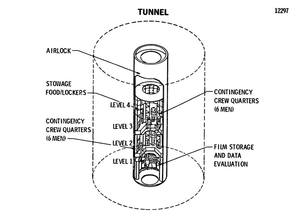
The core module tunnel has many functions other than that of being the main traffic artery. Contingency provisions are available should habitation of this compartment be required.
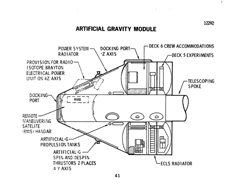
Similar to the forward half of the core module, the artificial-gravity module contains a two-deck module and a conical section containing a propulsion system to provide the spin necessary for artificial-gravity operation. This conical section also has provisions to increase the electrical power capability of the Space Station through the later addition of one or more isotope/Brayton units. Initially, Deck 6 is configured as a crew and operations facility for the artificial-gravity experiment. When the equipment used in the crew and operations facility is stowed, the volume can be converted to accommodate additional research facilities. If the need arise to accommodate a larger crew (up to 18 men), this deck can be reconverted to a crew facility. Two centrifuges occupy Deck 5.
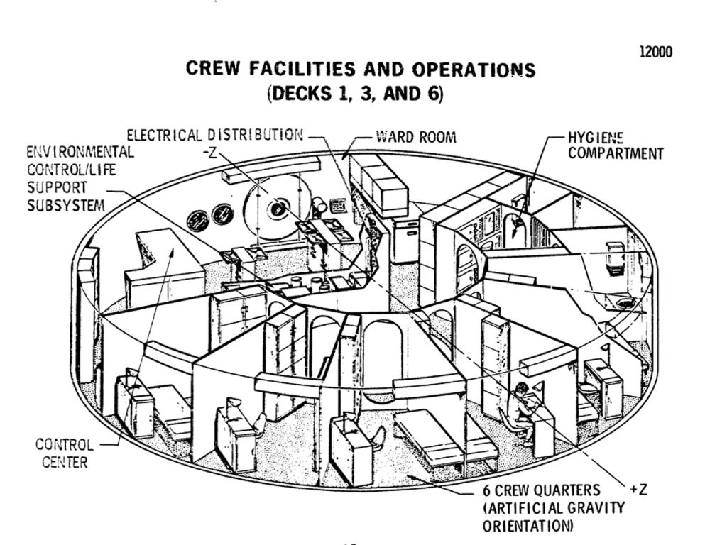
One deck in each of the three modules is configured to support the crew. Facilities on each deck are sized to provide private quarters and eating and hygiene facilities for six men. However, the life support system will accommodate the entire crew of twelve on any deck. The layout is shown for the artificial-gravity module.
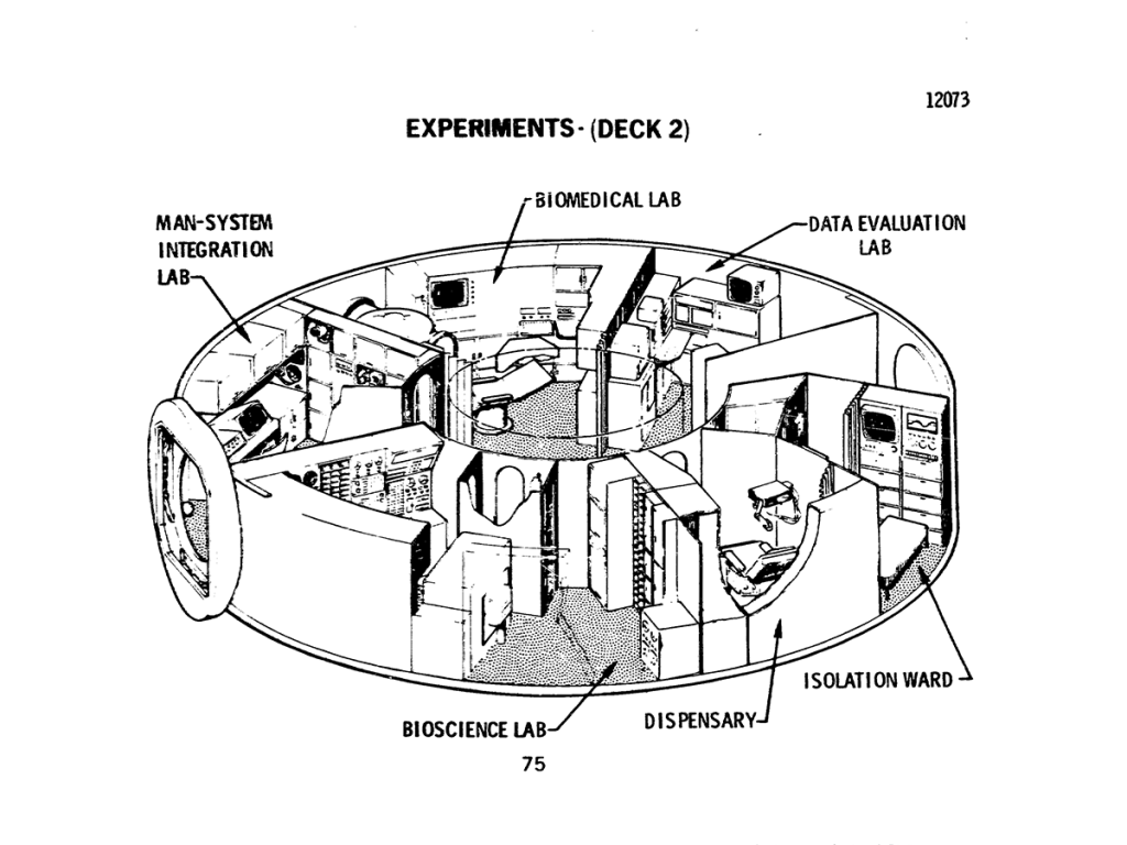
Deck 2 is dedicated to experiment activities associated with the study of various life forms in zero activity. man, animals, plants, micro organisms are all subjects for analysis. Considerations of equipment and facility commonality result in locating the dispensary and isolation ward adjacent to these laboratories.
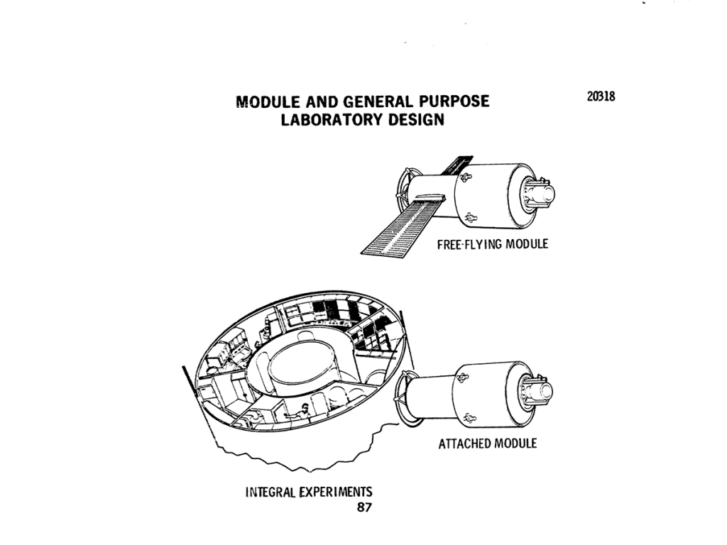
Experiments may be accommodated either within the Space Station or in attached or free flying modules that use services provided by the Space Station. Internal experiments are either launched with the Space Station or brought up layer by the logistics system, transferred aboard, and installed; all attached and free-flying modules are delivered to orbit by the logistics system.
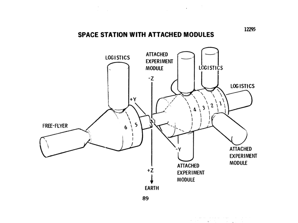
The Space Station contains a total of eight docking ports; these ports are of a universal design to accommodate either crew/cargo modules or attached to free-flying experiment modules. Normally, logistics modules will dock on the artificial gravity module and the aft end of the core module. The free-flying experiment modules will share the forward docking port, while all attached modules dock to the core module.
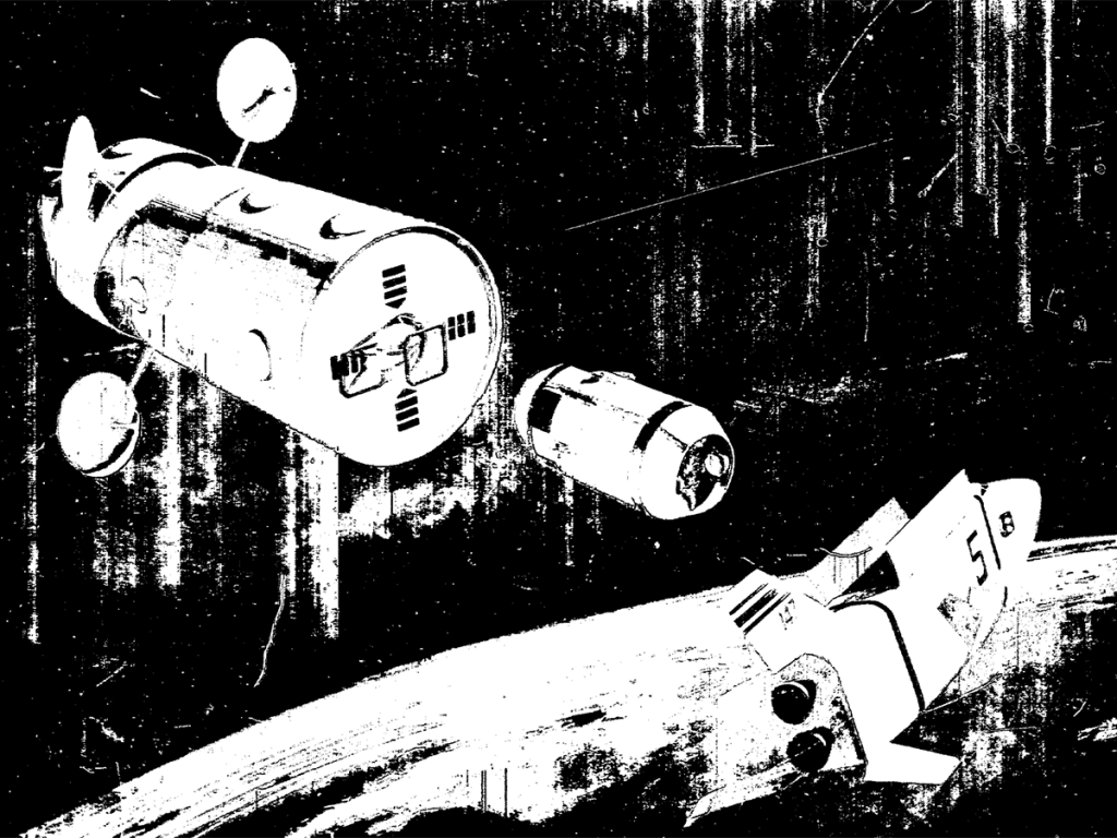
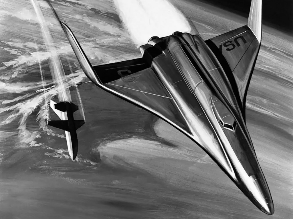
The orbiter is seen separating from the booster stage, which now prepares to return to Earth.
A typical payload for the logistics system is an experiment module leaving the cargo bay. Its propulsion system has ignited as it makes its guided way to the station.
Image credit: McDonnell Douglas
Image source: NASA NTRS
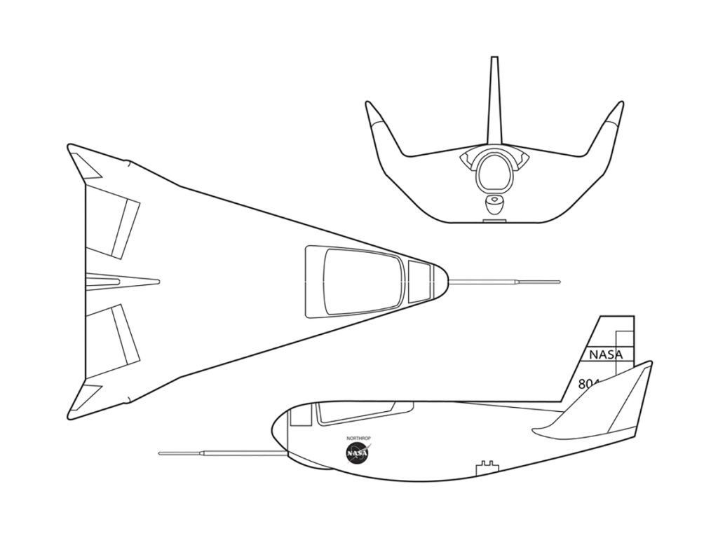
The HL-10 was one of five aircraft built in the Lifting Body Research Program. It was a NASA design and was built to evaluate an inverted airfoil lifting body with a delta planform. The HL-10 was flown 37 times during the program and logged the highest altitude and fastest speed.
EG-0053-01
The HL-10 was one of five aircraft built in the Lifting Body Research Program. It was a NASA design and was built to evaluate an inverted airfoil lifting body with a delta planform. The HL-10 was flown 37 times during the program and logged the highest altitude and fastest speed.
The other lifting body designs were the M2-F2, M2-F3 (rebuilt M2-F2 following a landing accident), X-24A and X-24B (the rebuilt X-24A with a different aerodynamic shape).
The HL-10 was flown 37 times during the lifting body research program and logged the highest altitude and fastest speed in the Lifting Body program. On Feb. 18, 1970, Air Force test pilot Peter Hoag piloted the HL-10 to Mach 1.86 (1,228 mph). Nine days later, NASA pilot Bill Dana flew the vehicle to 90,030 feet, the highest altitude reached in the program.
Some new and different lessons were learned through the successful flight testing of the HL-10. These lessons, when combined with information from it’s sister ship, the M2-F2/F3, provided one option for designers of future atmospheric re-entry vehicles.
Image credit: NASA FRC
Image source: NASA
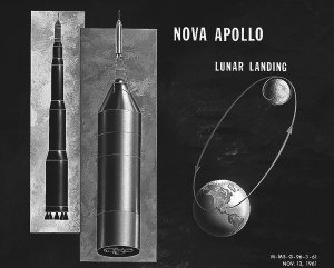
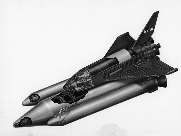
This artist’s concept illustrates the Module Nova concept – Solid C-3 Basis. From 1960 to 1962, the Marshall Space Flight Center considered the Nova launch vehicle as a means to achieve a marned lunar landing with a direct flight to the Moon. Various configurations of the vehicle were examined. The latest configuration was a five-stage vehicle using eight F-1 engines in the first stage. Although the program was canceled after NASA planners selected the lunar/orbital rendezvous mode, the proposed F-1 engine would eventually be used in the Apollo Program to propel the first stage of the Saturn V launch vehicle.
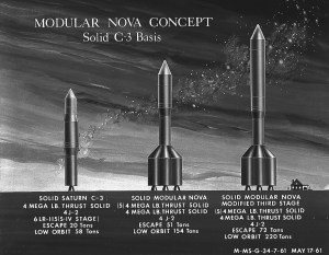
This artist’s concept illustrates the Module Nova concept – Solid C-3 Basis. From 1960 to 1962, the Marshall Space Flight Center considered the Nova launch vehicle as a means to achieve a marned lunar landing with a direct flight to the Moon. Various configurations of the vehicle were examined. The latest configuration was a five-stage vehicle using eight F-1 engines in the first stage. Although the program was canceled after NASA planners selected the lunar/orbital rendezvous mode, the proposed F-1 engine would eventually be used in the Apollo Program to propel the first stage of the Saturn V launch vehicle.
Image credit: NASA MSFC
Image source: NASA Images

Concept art by Ron Simpson.
In December 1968, NASA convened the Space Shuttle Task Group which set out the basic missions and characteristics of a reusable launch system, borrowing the term ILRV from the Air Force studies. Development would take place in four phases; Phase A: Advanced Studies; Phase B: Project Definition; Phase C: Vehicle Design; and Phase D: Production and Operations.
Each of the agencies involved favored different configurations for the shuttle: The FDL and Draper Laboratories favored a swept delta wing spaceplane, like the Dyna-Soar, for maximum cross range on re-entry. NASA Langley and Edwards AFB favored a lifting body, based on the HL-10 then under test which had a weight advantage but lower cross range.
A Request for Proposal was issued jointly by NASA Houston and NASA Huntsville in January 1969, for an eight-month Phase A study. General Dynamics, Lockheed, McDonnell Douglas, Martin Marietta, and North American Rockwell won ILRV study contracts. The ILRV was to be capable of delivering propellent, propulsive stages and payloads to orbit, orbital launch and retrieval of satellites, satellite maintenance, space station logistical support and short duration crewed missions. The report considered three classes of vehicles: reusable orbiters launched on expendable boosters, stage and a half vehicles and two-stage vehicles where both the booster and orbiter were fully reusable. Martin Marietta’s design was ultimately dropped, but they continued to develop their vehicle using company funds.

After further study, General Dynamics abandoned the Triamese design in September as it had proven difficult to make one aerodynamic shape serve both as a booster and orbiter. After a contract extension, the company settled on a more traditional two-stage v-tailed design.
Lockheed’s Phase A contract concentrated on fully reusable versions of the STAR Clipper. Their final design was a delta-planform lifting-body orbiter paired with a body-wing booster.
Martin Marietta developed the Spacemaster, an orbiter based on the X-24B with an unusual catamaran style booster.
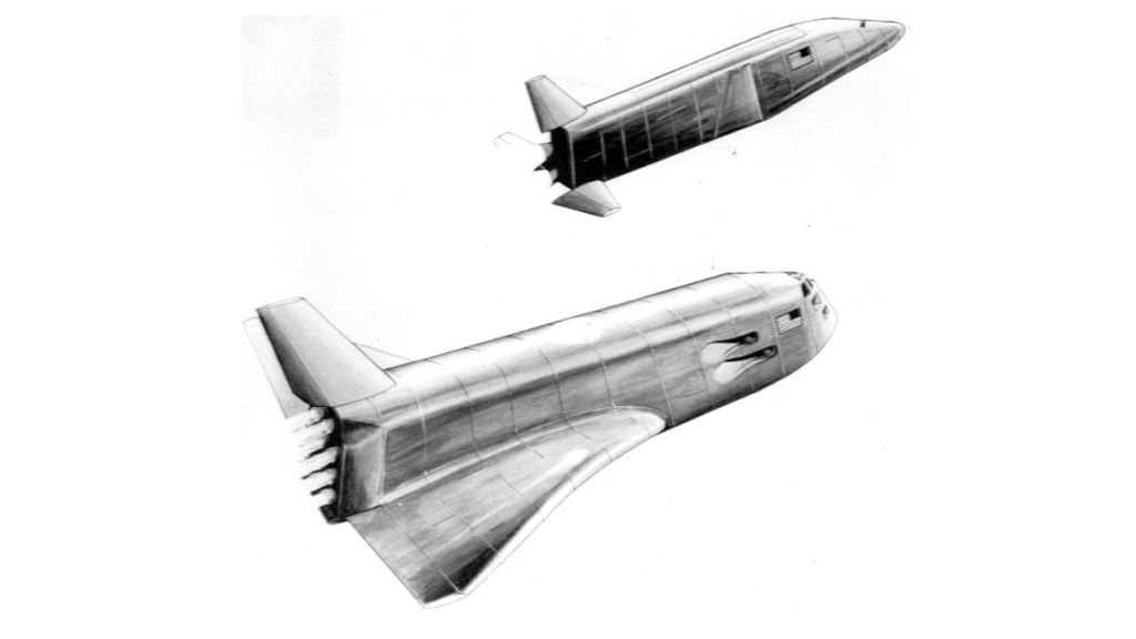
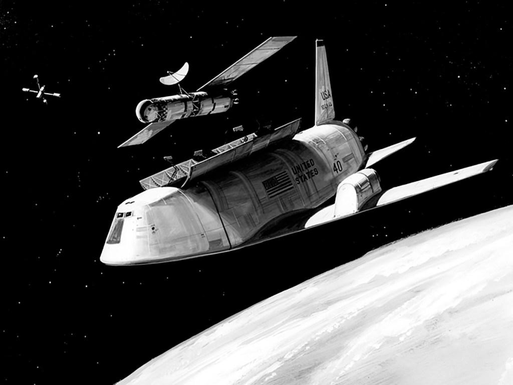
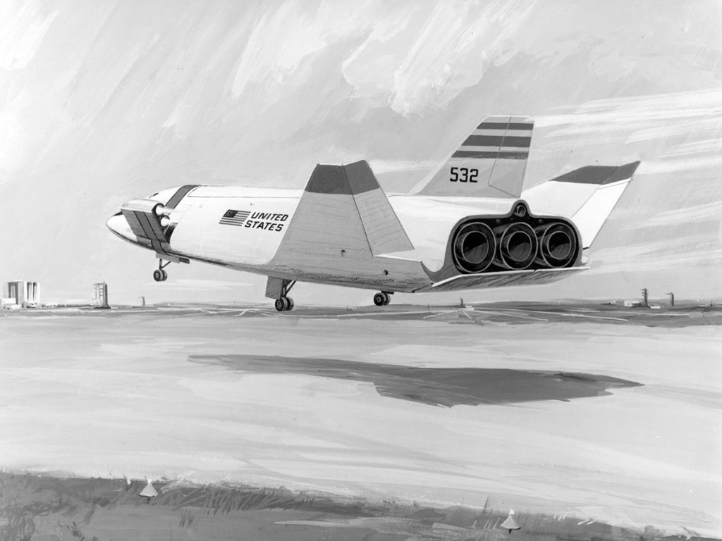
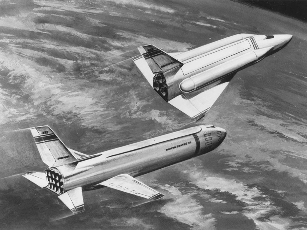
McDonnell Douglas studied partially reusable designs early in Phase A, receiving additional funding in July 1969 to investigate Langley’s HL-10 Lifting Body. The company additionally proposed a number low cost designs. The “drawbridge” orbiter would re-enter with folded wings for high cross-range military missions, and unfolded wings for low cross-range missions when the heat loads would be lighter. A smaller alternative design was derived from their 1968 ILRV proposal.
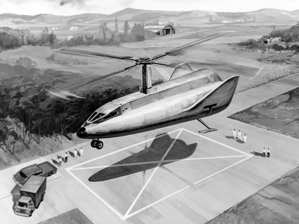
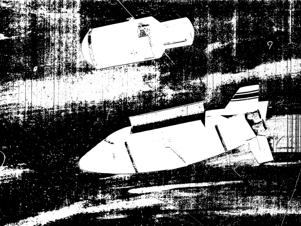
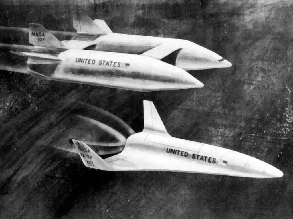
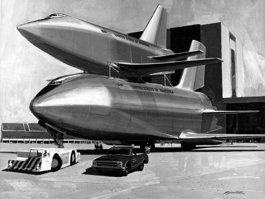
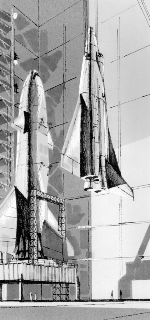
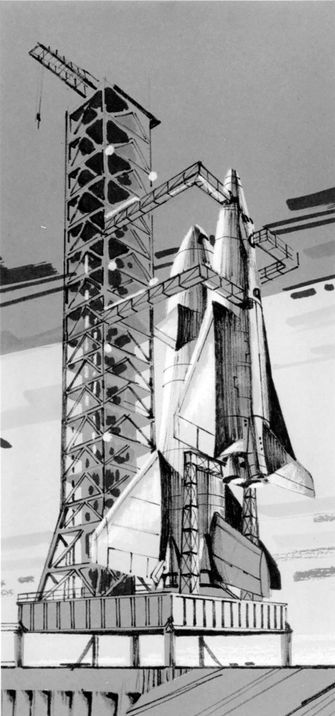
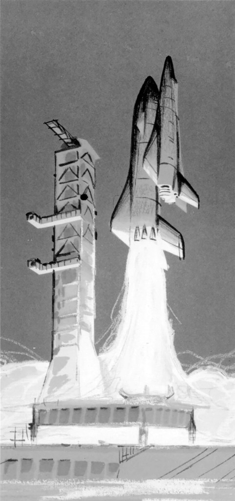
Initially focused on partially reusable designs, in June North American received additional funding from NASA to investigate a concept by the Manned Space Center’s Maxime Faget. Faget disliked the lifting-body designs for their poor low speed handling and believed they would be difficult to develop. Faget’s more conventional design was flat-bottomed with low-mounted swept wings. The vehicle would re-enter the atmosphere in a nose high attitude, presenting its lower surfaces to the airflow to blunt its descent. As the vehicle reached the lower atmosphere, it would pitch forward to a conventional flying attitude with jet engines powering the vehicle to a landing. He called his design the DC-3. In July, North American received additional funding to develop modular space station and space base concepts.
The cancellation of the X-20 in December 1963, and MOL in June 1969 left the Air Force without a manned space program of its own and demonstrated a need to cooperate with NASA in order to place military astronauts in orbit. NASA in turn sought Air Force support. In October NASA and the Air Force agreed to develop a reusable space vehicle that would meet both civilian and military requirements, and in so doing create a national system.
As development progressed, Air Force involvement began to shape design. The Airforce high cross-range requirement necessitated a large delta wing, which effectively eliminated the DC-3 and FR-3A from consideration.
A meeting was held in Houston to study all the in-house concepts. Over the next year, several designs were dropped including the entire series of lifting-body derived vehicles.
NASA now stipulated a fully reusable system with both component vehicles being able to undertake ferry flights between landing and launch sites, ending any consideration of a partially expendable system. Funding was awarded to consortiums led by North American Rockwell, and McDonnell Douglas. In addition, both teams were instructed to study alternate orbiters: the straight-wing low cross-range Faget design and delta wing configurations for high cross-range missions.

Martin Marietta’s booster was derived from an alternative Spacemaster booster concept, with jet engines mounted inside the forward canard to improve weight distribution during recovery. The all-metal orbiter featured a large delta wing and a single vertical stabilizer.
The NAR 130 straight-wing low cross-range design remained as a secondary option as late as 1971.
NAR 134-B was a high cross-range vehicle with a payload capacity of 9,072kg, capable of making powered or unpowered glide landings.
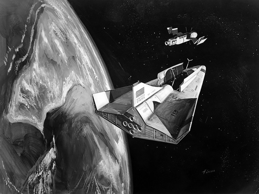
North American’s NAR 161-B orbiter carried a crew of two and up to ten passengers in a forward module. Four deployable jet engines mounted on top of the fuselage gave it a go-around capability. General Dynamic’s B9U booster was a significant evolution of its B8D concept. The straight wing was replaced with a delta wing to improve stability through all phases of the flight. The landing jets were moved from the nose back to the wing to reduce drag.
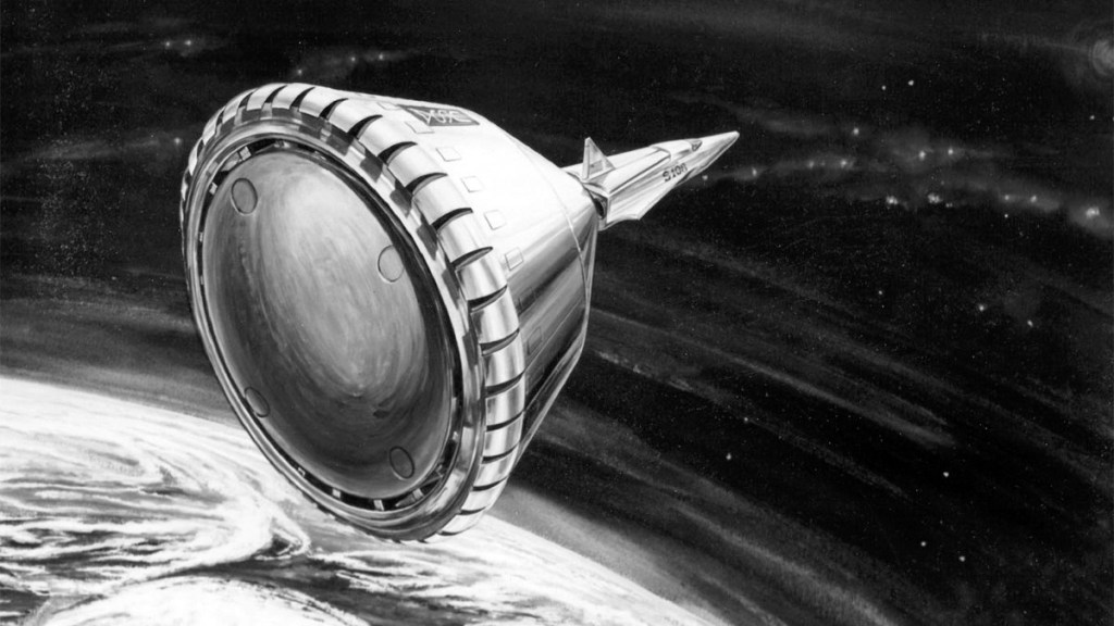
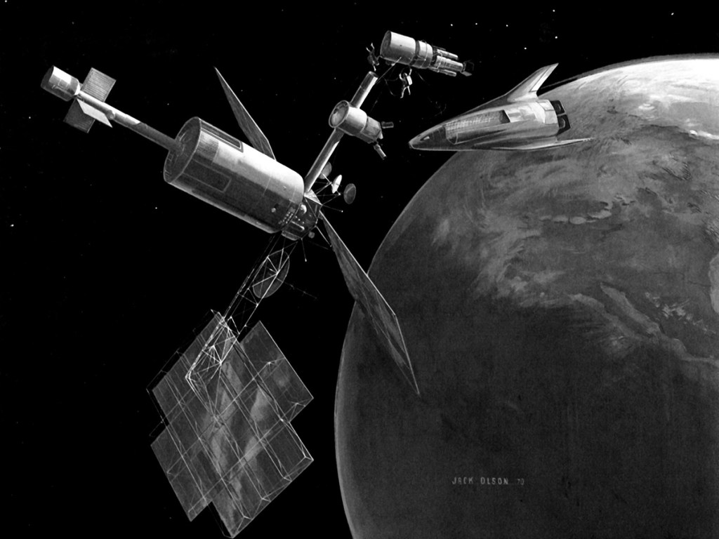
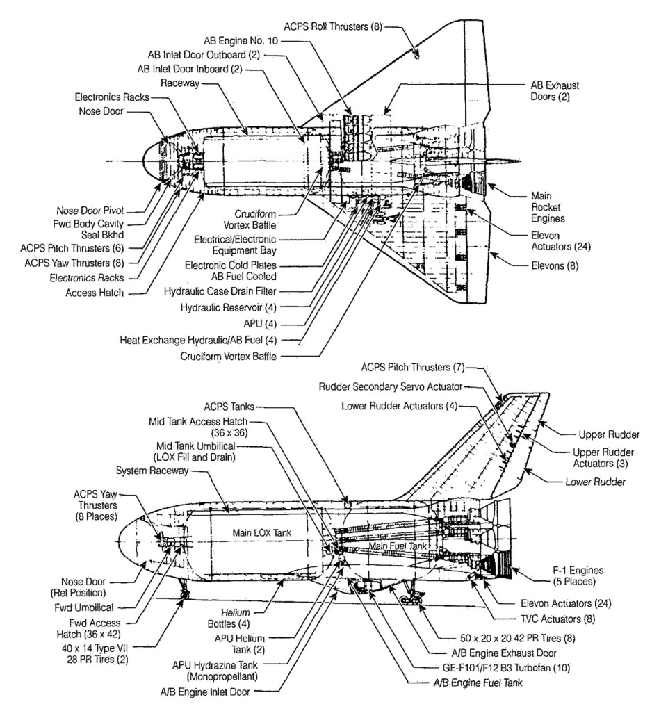
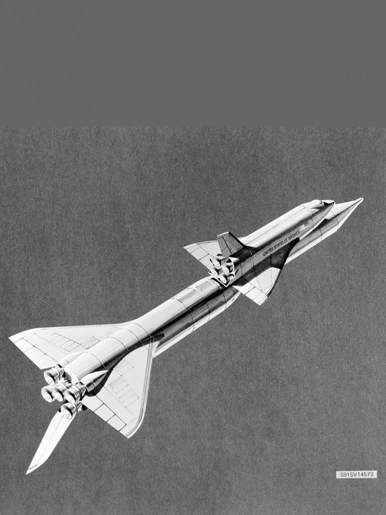
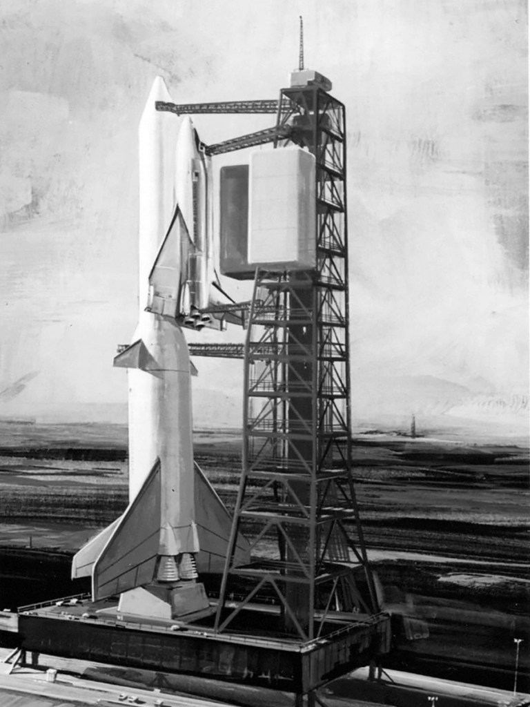
Chrysler’s Single-stage Earth-orbital reusable Vehicle (SERV) was a launch system capable of carrying up to 125,000 lbs of cargo. SERV had a large conical body with a rounded base, covered with ablative screw-on panels. A twelve module LH2/LOX aerospike engine was used during ascent, a ring of jet engines slowed the vehicle’s descent prior to touchdown. The original proposal used a lifting body spaceplane based on the HL-10 called MURP to support manned missions. A later version paired SERV with a personnel module based on the Apollo CSM.
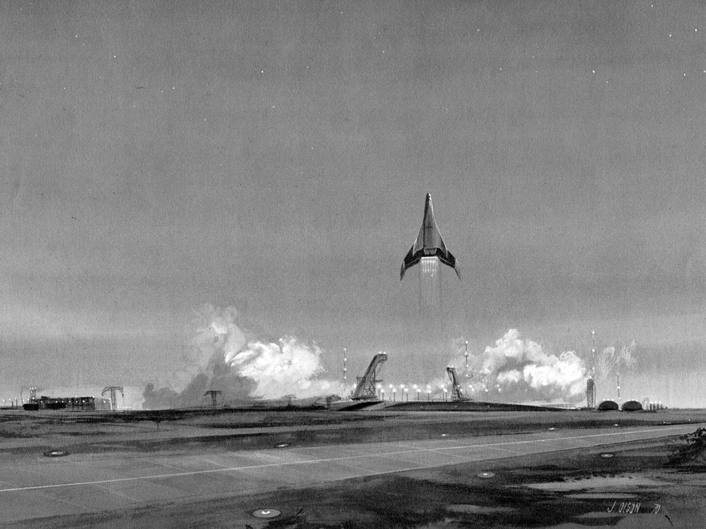
1970 artwork by Boeing artist John J. Olson
After partnering with Boeing for a failed Phase B bid, Lockheed was awarded a contract under the Alternate Space Shuttle Concepts (ASSC) study in July 1970. The study focused on partially expendable designs as a fallback should the TSTO configurations prove too challenging or costly.
In December 1970 Grumman and Boeing received a contract to study two-stage-to-orbit shuttle configurations using both internal and external liquid hydrogen tanks. In review with NASA, Boeing and Grumman demonstrated that equipping the orbiter with an external drop-tank would lead to a significant reduction in the weight, size, development risk and cost of both vehicles. In April NASA authorized Boeing and Grumman to make a detailed study of the most promising configuration: a three-engine orbiter with an external liquid hydrogen tank and heat-sink booster.
NASA’s budget is capped by the Office of Management of the Budget for the next five years, effectively ending development of a fully reusable shuttle.
McDonnell Douglas and North American Rockwell both received contract extensions in March 1971 to study the impact of Grumman’s drop tank concept on their Phase B designs.
While the LS-200 design had been shelved, Lockheed received funds to continue working on drop-tank and solid rocket booster configurations.

Fully-reusable shuttle orbiter with the S-IC used as an interim first stage. Painting by Grumman artist Craig Kavafes.
Boeing and Grumman investigated the Saturn S-1C interim booster concept as well as various combinations of drop tanks and boosters. Boeing also unveiled a shuttle booster design in August 1971 dubbed RS-1C, which would have put wings, landing gear and jet engines on the S-1C booster, transforming it into a flyback booster.
Winged S-IC stage. (Boeing)
RFPs were sent to Grumman / Boeing, McDonnell Douglas / Martin Marrietta, and North American Rockwell for final proposals for Shuttle full-scale development.
Grumman / Boeing, Lockheed, McDonnell Douglas / Martin Marrietta, and North American Rockwell were issued contracts to study lower cost booster concepts: a fully recoverable booster stage, a modified Saturn V stage to serve as a flyback booster, and solid rocket motors.
The RFP for development of the orbiters and integration systems was released on March 17, 1972.
“As a design objective,” the RFP stated, “the Space Shuttle System should be capable of use for a minimum of 10 years, and each Orbiter Vehicle shall be capable of low cost refurbishment and maintenance for as many as 500 reuses.”
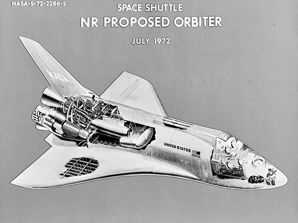
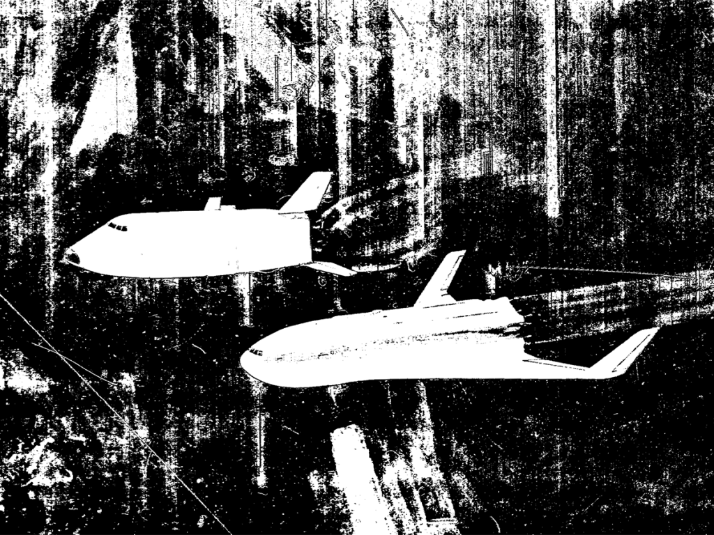
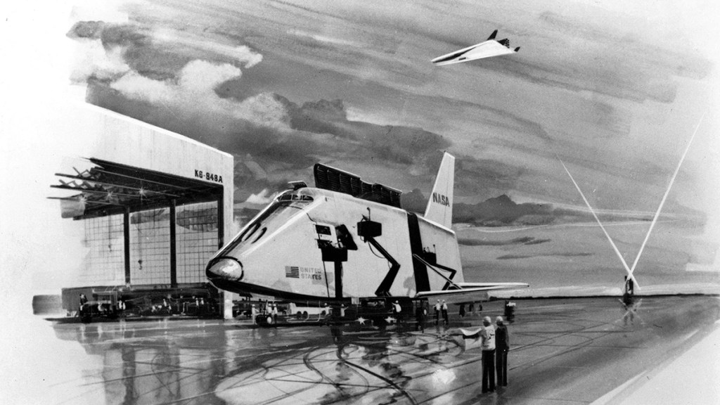
Final proposals by (left) North American Rockwell and (right) McDonnell Douglas.
The responses were due on May 12, and four companies replied: Grumman, Lockheed, McDonnell Douglas and North American Rockwell.
Grumman gained the highest score in the technical areas. Its structural layouts showed a thorough understanding of potential
problems and positive solutions. Grumman, however, was less outstanding in cost and management, the proposed cost was higher than NASA liked.
Lockheed’s bid ranked fourth in the competition, it was heavy and NASA Administrator James Fletcher considered that
its design had “unnecessary complexity.” Lockheed was also was the only bidder with no experience in building
piloted spacecraft
The final McDonnell Douglas proposal projected a relatively high cost, and showed technical weaknesses. The provisions in the proposal for maintainability of the Shuttle failed to adequately make use of the expertise Douglas had gained building the DC-10 airliner. McDonnell Douglas came away ranked third in the competition.
North American’s concept showed weaknesses, such as a crew cabin that would be difficult to build, but the design provided the lightest dry weight of any of the designs submitted, at the lowest cost of the four.
On July 16, 1973, the RFP for design and development of the SRM was issued to Aerojet Solid Propulsion, Lockheed, Thiokol, and United Technologies. NASA selected the Thiokol Chemical
Company.
References
The Space Shuttle Decision T.A. Heppenheimer NASA SP-4221
Shuttle, Encyclopedia Astronautica
Volume IV: Accessing Space Edited by John M. Logsdon, with Ray A. Williamson, Roger D. Launius, Russell J. Acker, Stephen J. Garber, and Jonathan L. Friedman. 1999
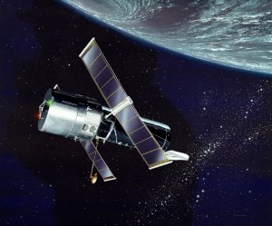
This illustration depicts a side view of the Hubble Space Telescope (HST). The HST is the product of a partnership between NASA, European Space Agency Contractors, and the international community of astronomers. It is named after Edwin P. Hubble, an American Astronomer who discovered the expanding nature of the universe and was the first to realize the true nature of galaxies. The purpose of the HST, the most complex and sensitive optical telescope ever made, is to study the cosmos from a low-Earth orbit. By placing the telescope in space, astronomers are able to collect data that is free of the Earth’s atmosphere. The HST detects objects 25 times fainter than the dimmest objects seen from Earth and provides astronomers with an observable universe 250 times larger than visible from ground-based telescopes, perhaps as far away as 14 billion light-years. The HST views galaxies, stars, planets, comets, possibly other solar systems, and even unusual phenomena such as quasars, with 10 times the clarity of ground-based telescopes. The major elements of the HST are the Optical Telescope Assembly (OTA), the Support System Module (SSM), and the Scientific Instruments (SI). The HST is approximately the size of a railroad car, with two cylinders joined together and wrapped in a silvery reflective heat shield blanket. Wing-like solar arrays extend horizontally from each side of these cylinders, and dish-shaped anternas extend above and below the body of the telescope. The HST was deployed from the Space Shuttle Discovery (STS-31 mission) into Earth orbit in April 1990. The Marshall Space Flight Center had responsibility for design, development, and construction of the HST. The Perkin-Elmer Corporation, in Danbury, Connecticut, developed the optical system and guidance sensors. The Lockheed Missile and Space Company of Sunnyvale, California produced the protective outer shroud and spacecraft systems, and assembled and tested the finished telescope.
Image credit: NASA KSC
Image source: NASA Images
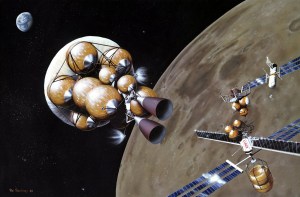
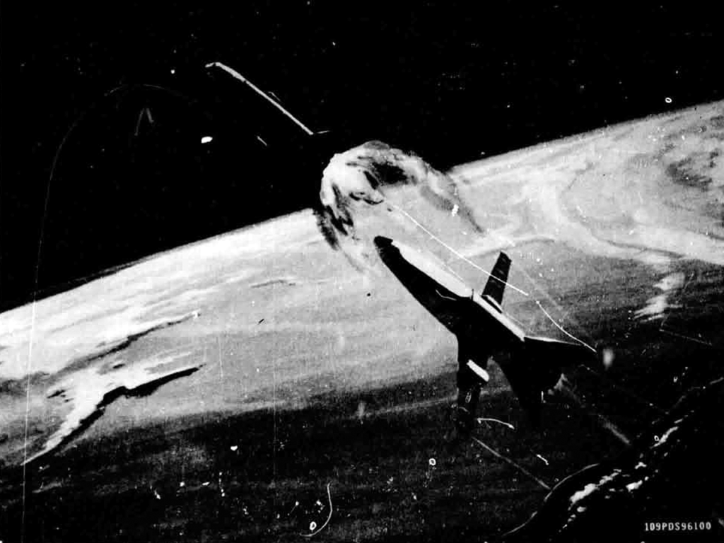
S83-28321 (14 March 1983) — In this artist’s concept of future lunar operations, a lunar ferry is about to burn out of lunar orbit for the trip back to facilities in low Earth orbit. The ferry vehicle carries tank modules filled with liquid oxygen, which has been produced from mining operations on the surface of the Moon. One possibility for such operations would be to have manned facilities in low lunar orbit, such as illustrated here. At the upper right side of the photo is a small orbiting manned station. At the lower right side of the photo is a liquid oxygen propellant dump, to which a lunar landing vehicle carrying liquid oxygen is about to dock. The lunar ferry vehicle itself is representative of one type of aerobraking system. The balloon-like torus around the center of the ferry-craft would inflate to several times its illustrated size and, once the vehicle has swooped down close to the Earth’s outer atmosphere on the return journey, would use atmospheric drag to slow the craft and place itself in low Earth orbit. The liquid oxygen would then be used in operations there for fueling various vehicles, including an orbital transfer vehicle for trips to geosynchronous Earth orbit. This concept is part of a study done for the Johnson Space Center by Eagle Engineering of Houston. The artist was Pat Rawlings.
Image credit: Eagle Engineering
Image source: Internet Archive
