There’s a section in the Solar Transportation that’s fascinating, as Ehricke describes a Mars capture mission. Everything is calculated; launch windows, vehicles, propulsion systems and a detailed plan for putting it all together in orbit are considered. Apart from graphs and a plan view of the core vehicle module, there’s no artwork in that section of the paper. One other irresistible aspect of Solar Transport is the reference section, where Ehricke lists – well – his references:
From 1962
Ehricke, K. A., Space Flight, Vol II, Dynamics, Chapter 9, Interplanetary Flight, Sec. 9-7: Fast Three-Dimensional Interplanetary Transfer Orbits; Sec. 9-8: Fast Reconnaissance Missions in the Inner Solar System; Sec. 9-9: Interplanetary Flights Involving Several Planets; Sect. 9-14: Capture Operations
From 1963
Ehricke, K. A., Perihelion Brake Maneuver, in a Study of Early Manned Interplanetary Missions, Final Summary Report, no. AOK-001, pp. 7-36/37, General Dynamics/Astronautics, Advanced Studies Office, January 1963
Ehricke, K. A., Study of Interplanetary Missions to Mercury Through Saturn with Emphasis on Manned Missions to Venus and Mars/82 involving Capture, General Dynamics/Astronautics Rep. GD/A 63-0916, September 1963. Paper presented at Symposium on Engineering Problems of Manned Interplanetary Exploration by AIAA, Palo Alto, Calif., September 1963
From 1964
Ehricke, K. A., A Study of Manned Interplanetary Missions, Part 2 of Proceedings of the Symposium on Manned Interplanetary Missions, 1963/64 Status; NASA TM-53049, June 12 1964 (abbreviated version of the internal document)
Ehricke, K. A., A Study of Manned Interplanetary Missions, Study Performance Contract NAS8-5026, January 1964: also A Study of Manned Interplanetary Missions, Contract NAS8-5026, Final Report, volume III, Mission Oriented Studies, July, 1964
Having described the velocity profiles and launch windows required for the MCM, the paper talks about vehicle requirements:
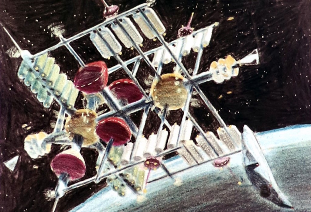
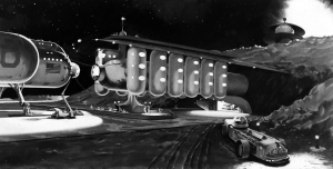
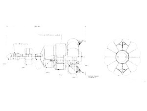
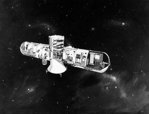
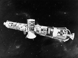
Interplanetary vehicles, whose mission duration requires from 400 to 6000 days, must have an extensive on-board checkout and repair facility located in the Life Support Section (LSS). By placing the LLS in orbit at the beginning of the orbital assembly process, this section serves at the orbit launch facility. In its initial form the LSS has two modifications, compared to its mission configuration which is shown in Figure 21a. Orbit launch preparation modules (OLPM) are attached; and an LSS maneuvering propulsion module occupies the space in which the mission version carries the Earth Entry Module (EEM). The Earth assembly version configuration of the LSS configuration are shown in Figure 21b.
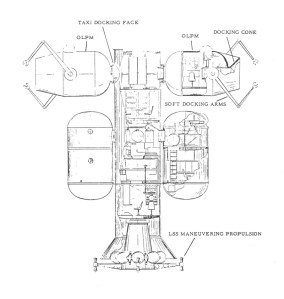
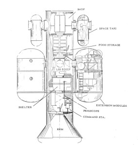
Fig 21a. Radial Life Support Section: Earth Assembly Configuration, acting as Orbit Launch Facility. Orbit Launch Preparation Modules (OLPM) will for mission, be replaced by Taxis. LSS Maneuvering Propulsion Module will be replaced by Earth Entry Module (EEM) (Reference 1964-12).
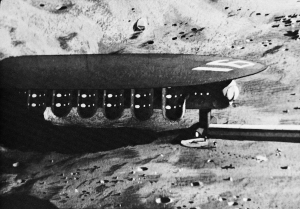
Fig 21b. Radial Life Support Section: Mission Configuration. Earth Entry Module (EEM) is located at forward end of Interplanetary Space Vehicle. Interface with propulsion section is rearward of the “shop”. External modules are jettisonable. (Reference 1964-12).
This is EMPIRE hardware, best described by David S.F. Portree in Humans to Mars which you can read for free at NASA History Division. Chapter 3: EMPIRE and After breaks down EMPIRE into delightful bite sized chunks and one of those chunks is about the General Dynamics contribution. I won’t try and paraphrase it, so just go and read Chapter 3. I’ll happily wait………
And now that you’re back, take a look at these images from A Study of Manned Interplanetary Missions and the report that contains it:
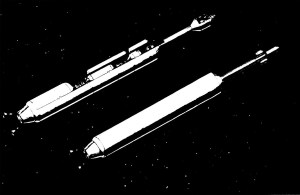
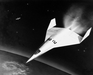
Venus Mission Vehicles
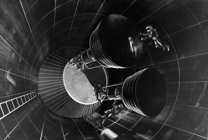
Fig. 2-1 Convoy consisting of Crew Vehicle and Service Vehicle (Cut-A-Way)
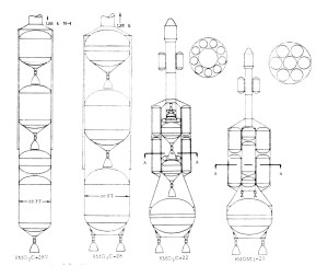
Fig. 2-2 Four basic configurations for interplanetary vehicles.
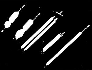
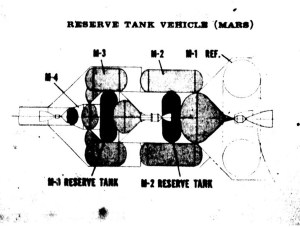
Mars Mission Vehicles
There are a couple of boxes in the Ehricke Papers that are really interesting because they appear to relate to the EMPIRE and UMPIRE studies, but they are presented without context. They’re undated and uncaptioned. What follows is my attempt to connect some of the dots. You might reach the same conclusions if you’ve read the same references I did. Your mileage may vary.
According to the report – and depending on the configuration – the launch vehicles would either be RIFT, NERVA, NOVA or Saturn boosters.
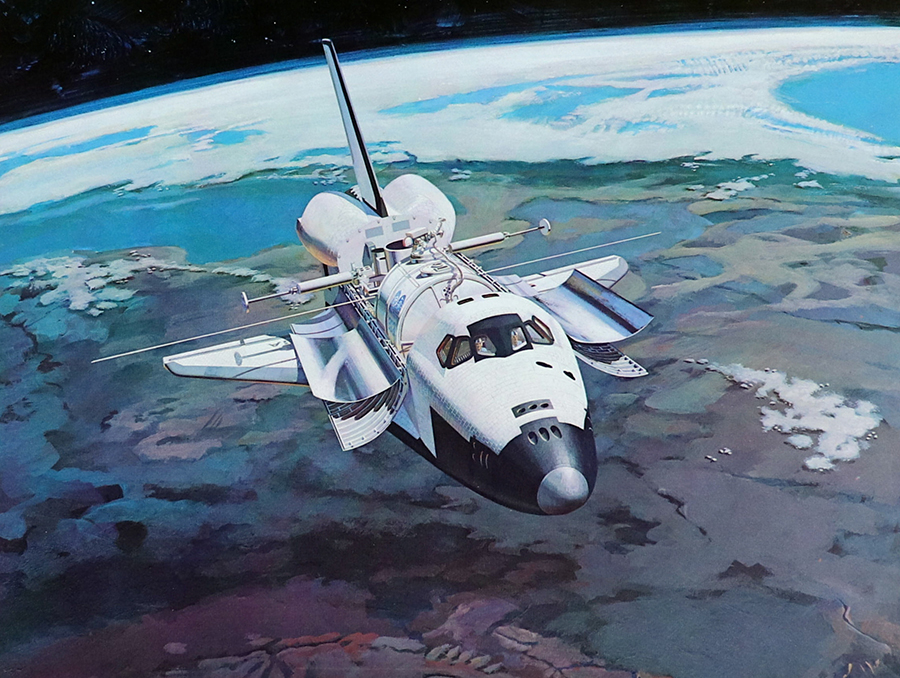
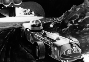
These paintings are from the Krafft Arnold Ehricke Papers and this is where our story starts:
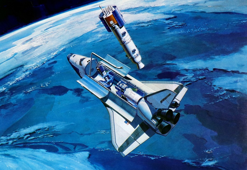
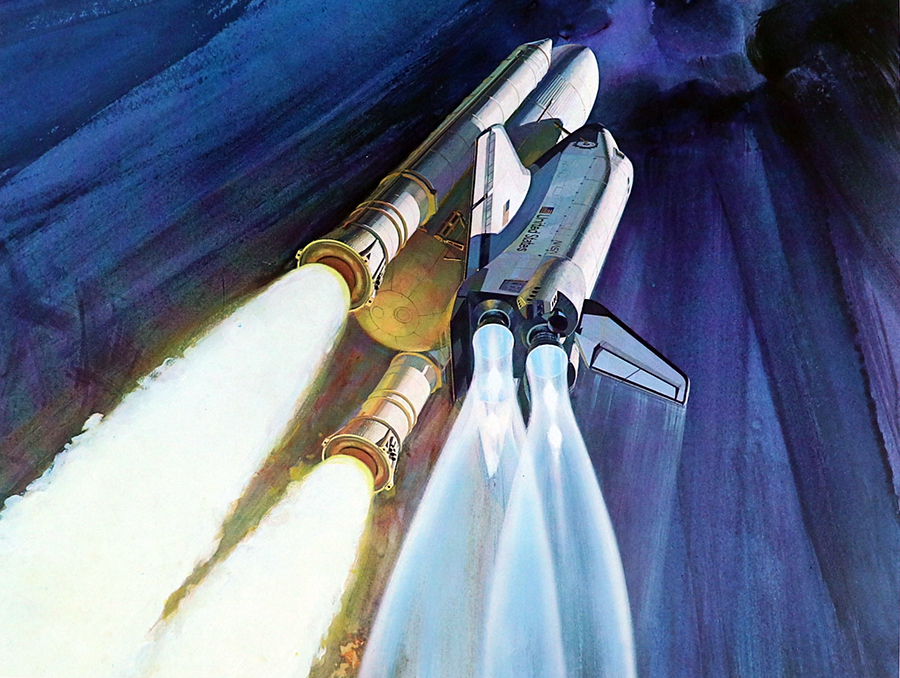
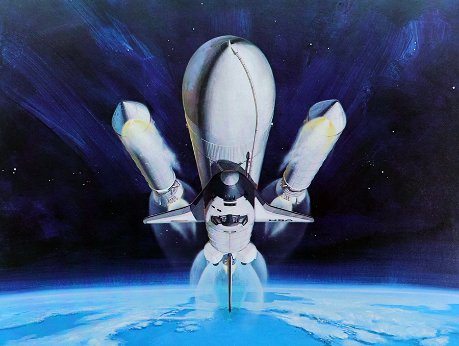
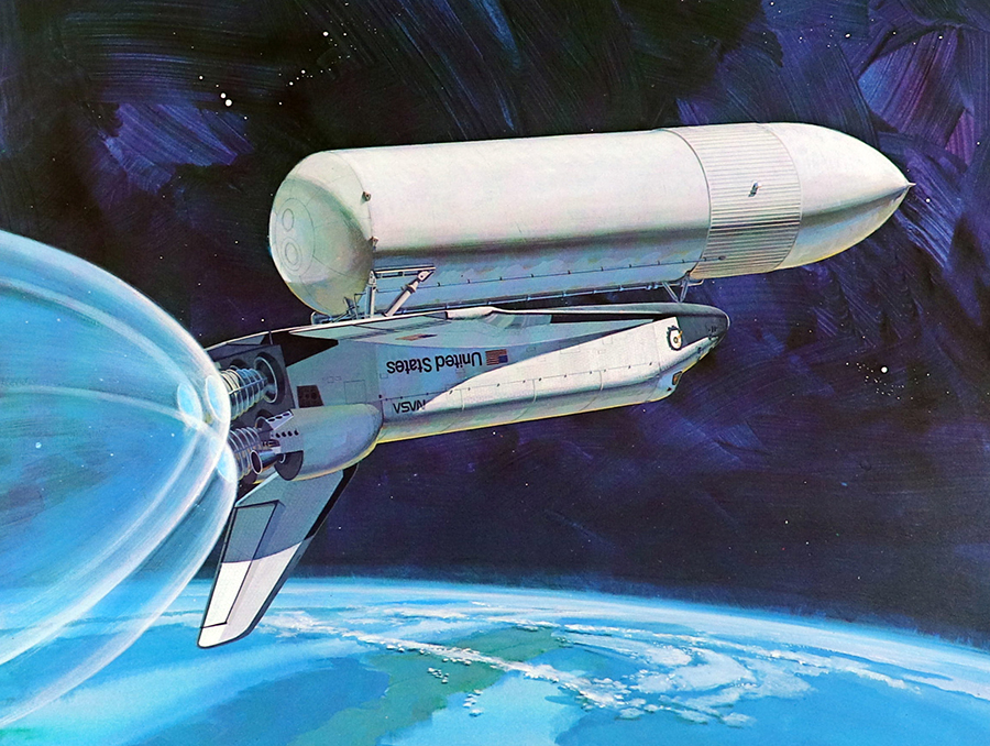
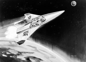
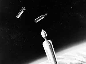
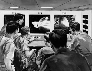
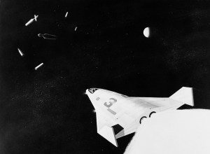
Equipment Launch into LEO
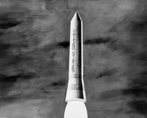
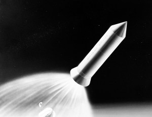

Above: Familiar artwork from (I believe) Ehricke’s time at Convair and most likely painted by John Sentovic. Below: Also from box one, this series appears to show the launch of the LSS by an unmanned rocket and arrival of the initial crew.
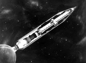
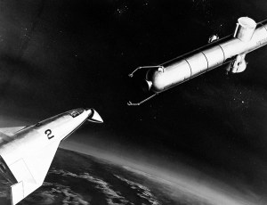
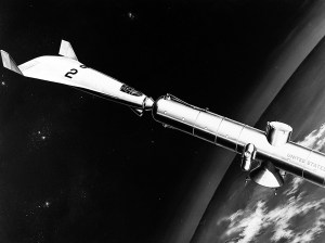
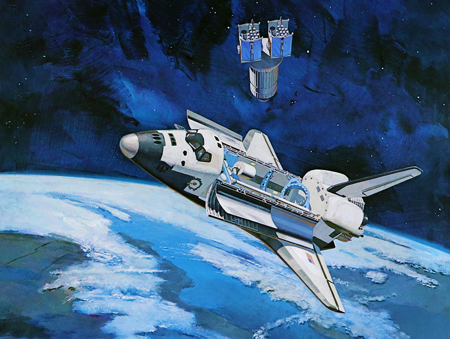
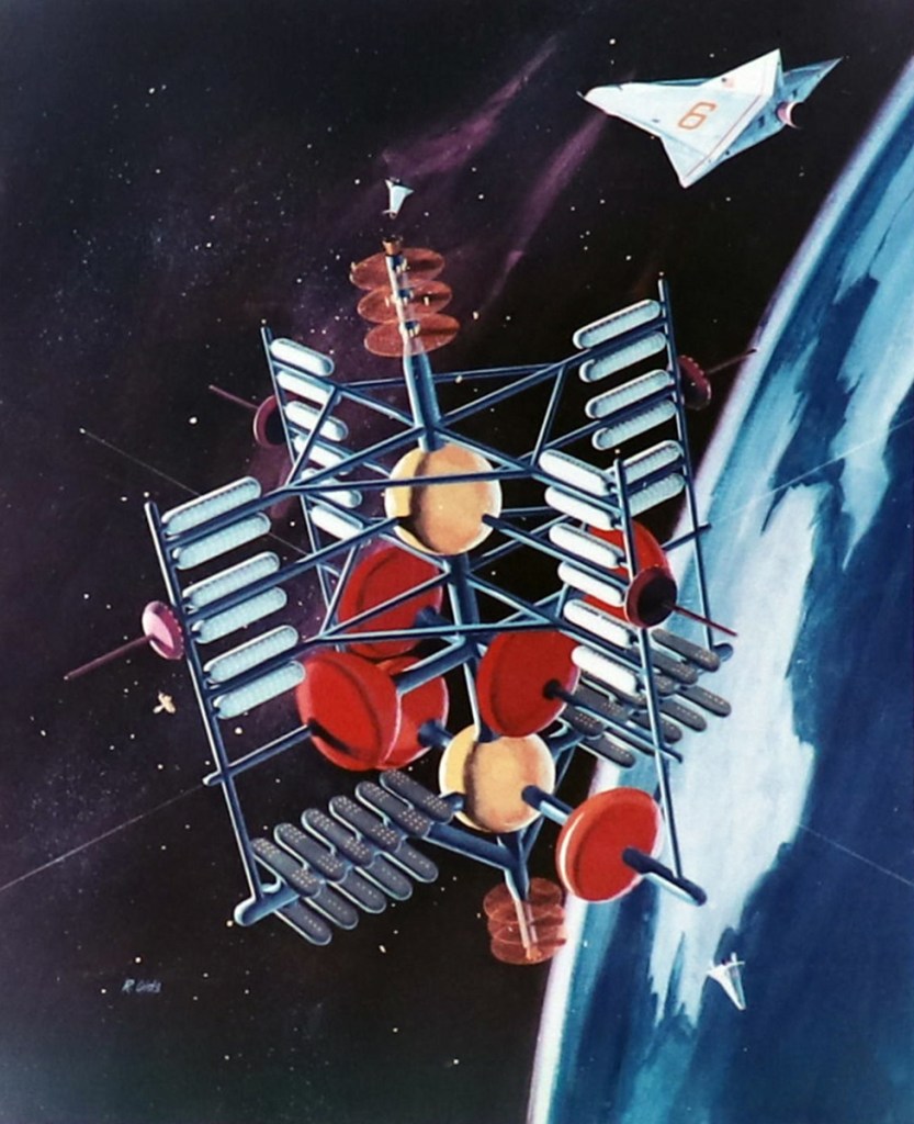
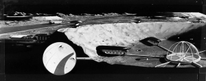
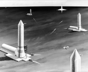
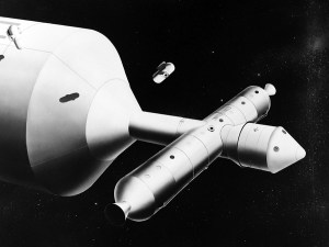
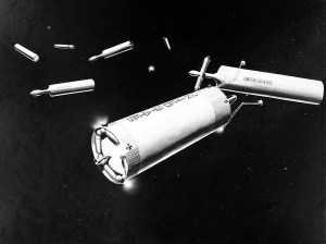
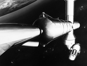
Vehicle Assembly
The EMPIRE vehicles would have been modular, assembled in LEO orbit before being sent along their way.

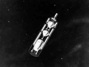
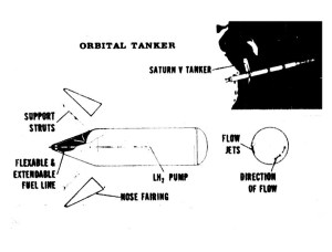
Above: The Propulsion Module combines with the Life Support Section to become – what’s referred to in Solar Transportation as – a Heliocentric Interorbital Space Vehicle or HISV. Below: Propulsion Modules arrive in orbit, vehicle assembly begins and the Orbital Tanker Vehicle begins fueling the fleet. Checkout complete, the mission crew arrive in a ferry vehicle.


Artists’ concepts (Spacecraft) [1 of 6 folders]
Image credit: Krafft Ehricke Papers
Image source: NASM