Image credit: General Atomics
File source: NASA NTRS
Image credit: General Atomics
File source: NASA NTRS
Lunar Ferry Vehicles
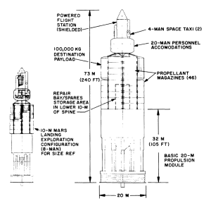
Fig. 3.13 — Exploration vehicle configuration for Jupiter moon landing mission, 20-m propulsion module
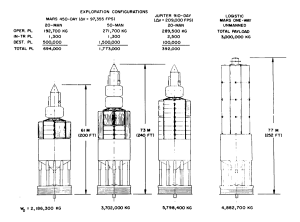
Fig. 3.15 — Various payload configurations on basic 20-m propulsion module (with departure weights for given missions)
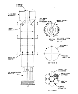
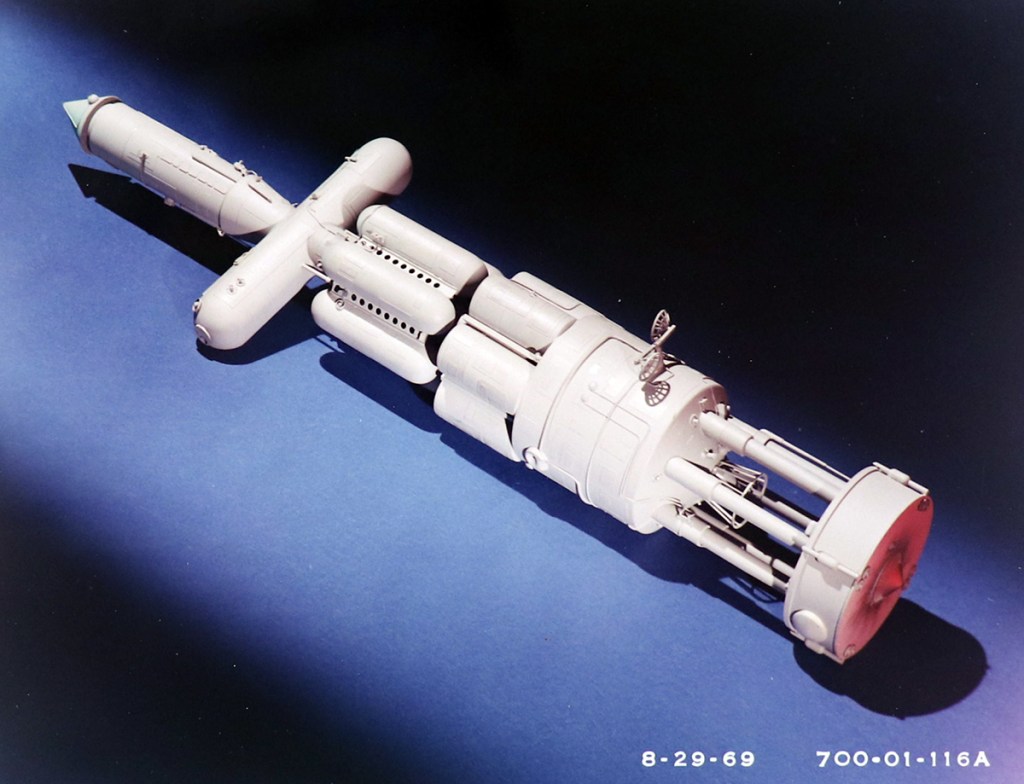
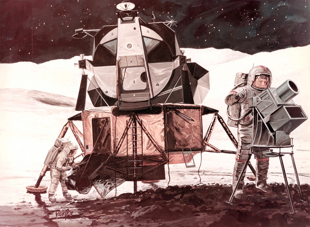
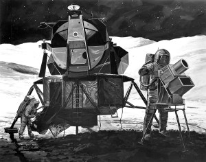
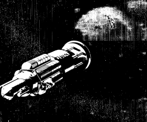
Fig. 3.16 — Earth-orbit-to-lunar-orbit ferry vehicle
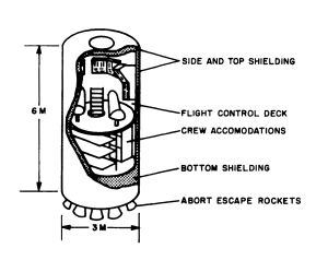
Fig. 3.18 — Lunar-ferry-vehicle command module
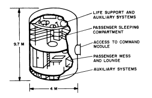
Fig. 3.19 — Reference-design passenger module
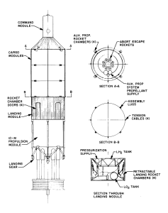
Fig. 3.20 — Earth-orbit-to-lunar-surface ferry vehicle
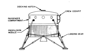
Fig. 3.21 — Lunar passenger ferry
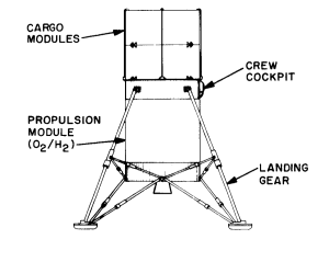
Fig. 3.22 — Lunar cargo shuttle
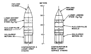
Fig. 3.23 — Solid-propellant-boosted earth-launched lunar logistic vehicles
Lunar Logistics Vehicles
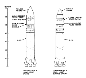
Fig. 3.24 — S-IC boosted earth launched lunar logistics vehicle
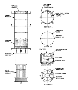
Fig. 3.15 — Orbit launched lunar logistics vehicle
From:
Nuclear Pulse Space Vehicle Study
Vol. III — Conceptual Vehicle Designs and Operational Systems (U)
Image credit: General Atomics
File Source: Cornell
Personnel Accommodations
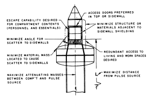
Fig. 3.2 — Factors that influence the location of the shielded powered flight station
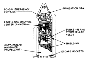
Fig. 3.4 — Powered flight station-escape vehicle for 8-man exploration missions with 10-m configurations
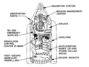
Fig. 3.5 — Powered flight station-escape vehicle for 20-man exploration missions with 20-m configurations
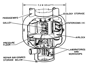
Fig 3.6 — Exploration-mission personnel accommodations for an 8-man complement
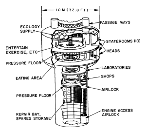
Fig 3.7 — Exploration-mission personnel accommodations for a 20-man complement
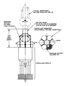
Fig 3.8 — General arrangement of payload spine and magazine payload support columns
Planetary Exploration Vehicles
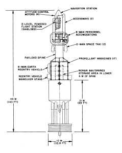
Fig. 3.11 — Exploration vehicle for Mars orbital capture mission using 10-m propulsion module
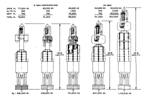
Fig. 3.12 — Various payload configurations on basic 10-m propulsion module (with departure weights for 72, 850 fps Mars mission)
From:
Nuclear Pulse Space Vehicle Study
Vol. III — Conceptual Vehicle Designs and Operational Systems (U)
Image credit: General Atomics
File Source: Cornell
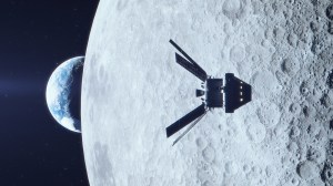
Image credit: NASA
Image source: NASA Orion