Pegasus Cutaway & Plan

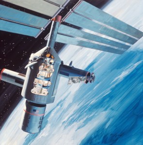
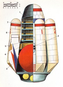
Pegasus Intercontinental Passenger Rocket

  1. Forward pressure dome;
  2. Two-man crew compartment;
  3. Re-entry stabilization fines (2);
  4. Cargo compartment;
  5. Aft pressure dome;
  6. Pressurized cabin for passengers (170);
  7. Deck structure (4) with passenger couches (43 each).

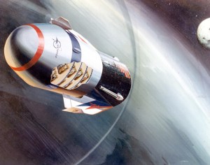
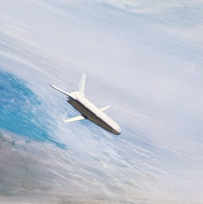
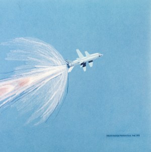
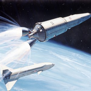
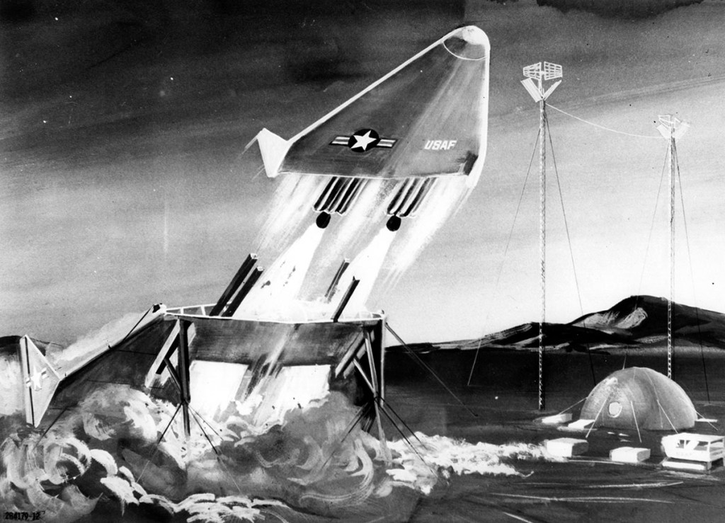
Pegasus during atmospheric re-entry uses the LH2-cooled plug nozzle as a heat shield. The ballistic transport would convey 172 passengers and freight 7,456 miles (12,000 km.) in 39 min. without exceeding an acceleration of 3g during ascent or re-entry. At the arrival spaceport it would hover on rocket thrust during a soft landing in the vertical attitude.

Pegasus Passenger Compartment

  1. Four-level passenger access doors (3);
  2. Stairways (2) connecting four passenger decks;
  3. Double-wall acoustic damping structure;
  4. Luggage racks (9);
  5. Re-entry stabilization fins (2).

Frontiers of Space
Philip Bono & Kenneth Gatland
Macmillan, 1969

Image credit: Douglas / Blandford Press
Images: Numbers Station, SDASM Archives

Concept by Henry Lozano Jr.

Image credit: North American Rockwell
Image source: Numbers Station

NAR Artist Concept

Image credit: North American Rockwell
Image source: Numbers Station

X-20 by Warren McCallister

FOR RELEASE AT 9:00 A.M., PDT, SEPTEMBER 22, 1960

DYNA SOAR GLIDER RE-ENTERING EARTH’S ATMOSPHERE

This is a Boeing artist’s impression of how the Dyna Soar manned space glider will look when it re-enters the earth’s atmosphere after a flight into space. Leading edges of the craft will glow from the heat created by the friction of the vehicle passing into the atmosphere. Dyna Soar will be boosted into space by a modified Titan intercontinental ballistic missile. After being separated from its booster, the glider will be left in a piloted, near orbital flight. Its pilot later could glide to a conventional landing at an Air Force base. The Boeing Company, under supervision of the Air Force, is prime contractor for the system and the glider. The Martin Company is prime contractor for the Titan booster.

— Boeing Airplane Company Photo

FROM:

News Bureau
Boeing Airplane Company
Seattle 24, Washington

Image credit: Boeing
Image source: Numbers Station

Design 619

Image credit: Grumman
Image source: Numbers Station

NAR Art Department

Image credit: North American Rockwell
Image source: Numbers Station

Shuttle Development

Image credit: North American Rockwell
Image source: Numbers Station

NAR Station & Shuttle

see also:

Image credit: North American Rockwell, NASA MSFC
Images: Numbers Station, NASA MSFC

X-20 Three-View

Boeing X-20 Dyna-Soar abandoned by the US Air Force in 1963 before flight trials could begin. Although ultimately intended for launching by Titan 3C, this one-man vehicle followed principles established by the Austrian engineer Dr Eugen Stänger a quarter of a century before. The project played an important part in developing aerodynamic and structural techniques for new-generation space-craft capable of maneuvering after re-entry from orbit. Length 35 ft (10.7m.) wingspan 20 ft (6.09m.); height (with wire-brush landing skis retracted) 8 ft (2.4m.).

Frontiers of Space
Philip Bono & Kenneth Gatland
Macmillan, 1969

Image credit: Macmillan
Image source: Numbers Station

NAR 1970

Image credit: North American Rockwell
Image source: Numbers Station