Image credit: General Dynamics
Image source: SDASM Archives
Image credit: General Dynamics
Image source: SDASM Archives
Image credit: Convair
Image source: SDASM Archives
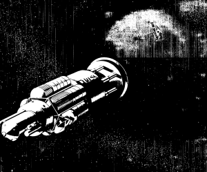
Image credit: General Atomics
File source: NASA NTRS
Lunar Ferry Vehicles
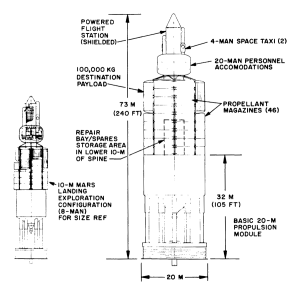
Fig. 3.13 — Exploration vehicle configuration for Jupiter moon landing mission, 20-m propulsion module
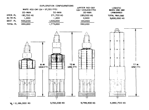
Fig. 3.15 — Various payload configurations on basic 20-m propulsion module (with departure weights for given missions)
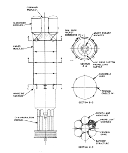
Fig. 3.16 — Earth-orbit-to-lunar-orbit ferry vehicle
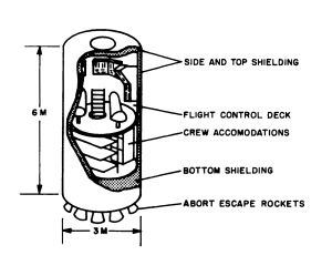
Fig. 3.18 — Lunar-ferry-vehicle command module
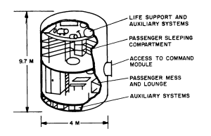
Fig. 3.19 — Reference-design passenger module
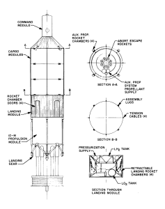
Fig. 3.20 — Earth-orbit-to-lunar-surface ferry vehicle
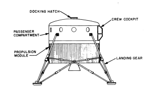
Fig. 3.21 — Lunar passenger ferry
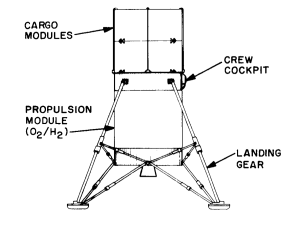
Fig. 3.22 — Lunar cargo shuttle
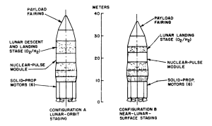
Fig. 3.23 — Solid-propellant-boosted earth-launched lunar logistic vehicles
Lunar Logistics Vehicles
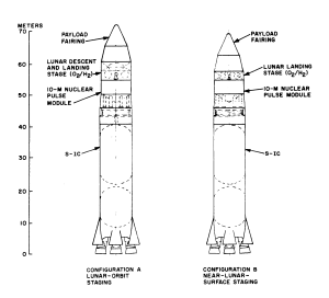
Fig. 3.24 — S-IC boosted earth launched lunar logistics vehicle
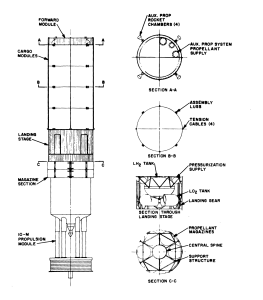
Fig. 3.15 — Orbit launched lunar logistics vehicle
From:
Nuclear Pulse Space Vehicle Study
Vol. III — Conceptual Vehicle Designs and Operational Systems (U)
Image credit: General Atomics
File Source: Cornell
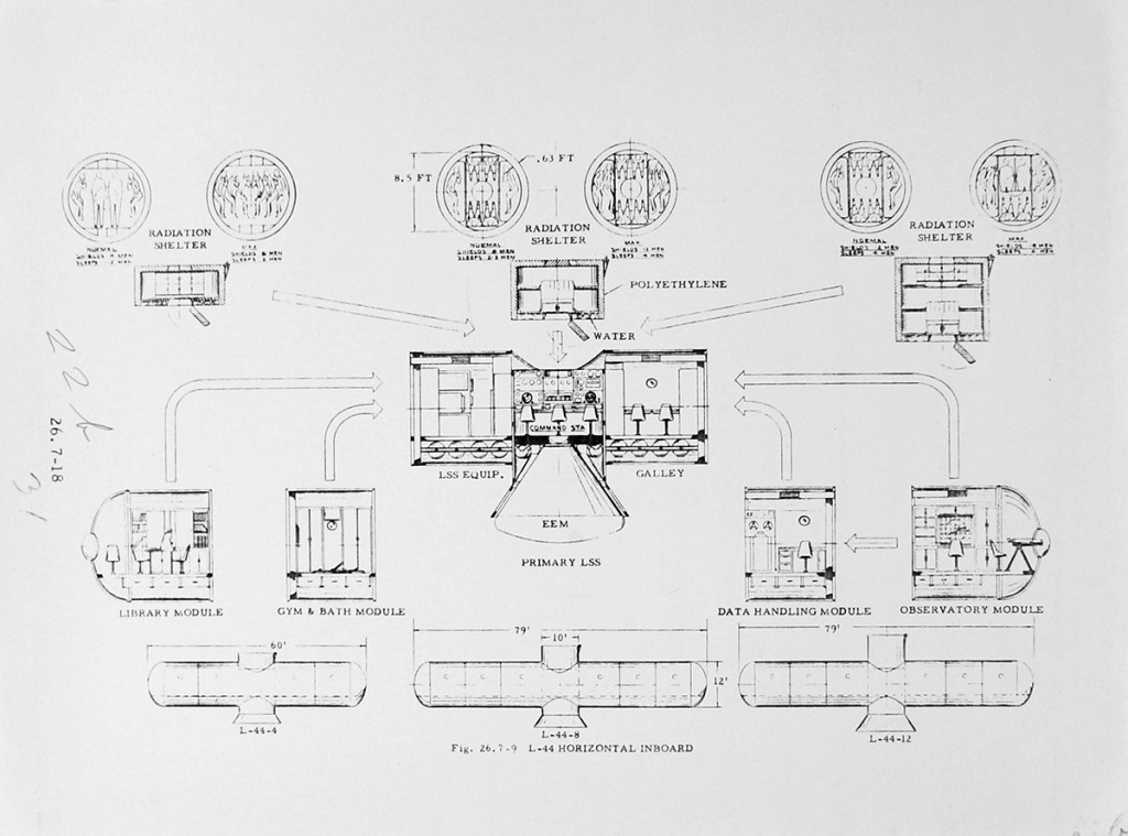
Personnel Accommodations
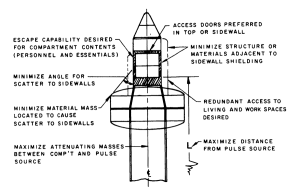
Fig. 3.2 — Factors that influence the location of the shielded powered flight station
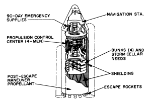
Fig. 3.4 — Powered flight station-escape vehicle for 8-man exploration missions with 10-m configurations
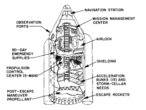
Fig. 3.5 — Powered flight station-escape vehicle for 20-man exploration missions with 20-m configurations
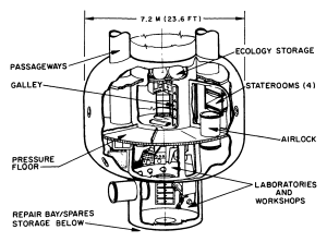
Fig 3.6 — Exploration-mission personnel accommodations for an 8-man complement
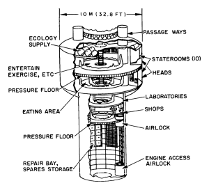
Fig 3.7 — Exploration-mission personnel accommodations for a 20-man complement
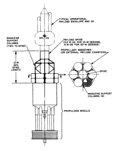
Fig 3.8 — General arrangement of payload spine and magazine payload support columns
Planetary Exploration Vehicles
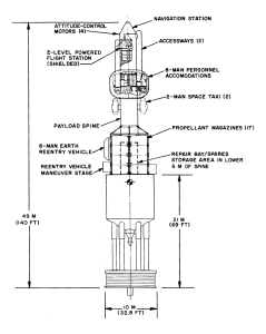
Fig. 3.11 — Exploration vehicle for Mars orbital capture mission using 10-m propulsion module
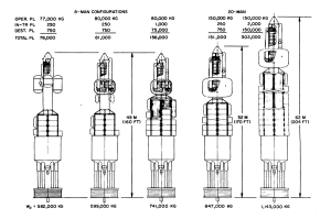
Fig. 3.12 — Various payload configurations on basic 10-m propulsion module (with departure weights for 72, 850 fps Mars mission)
From:
Nuclear Pulse Space Vehicle Study
Vol. III — Conceptual Vehicle Designs and Operational Systems (U)
Image credit: General Atomics
File Source: Cornell
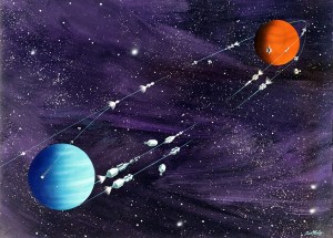
Image credit: General Dynamics / Astronautics
Image source: SDASM Archives

Mars Capture Mission in 1982. Orbit crew inspects the nuclear twin engine NERVA II system of the Earth Departure Module. Each engine delivers 250, 000 lbs. of thrust.
Image credit: Krafft Ehricke Papers
Image source: NASM
Artists’ concepts (spacecraft) [2 of 6 folders]
Vehicle Requirements
Image credit: Krafft Ehricke Papers
Image source: NASM
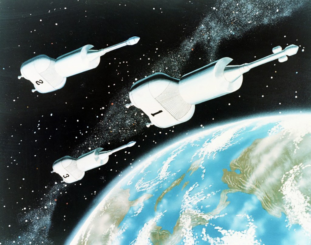
Image credit: General Dynamics / Astronautics
Image source: SDASM Archives
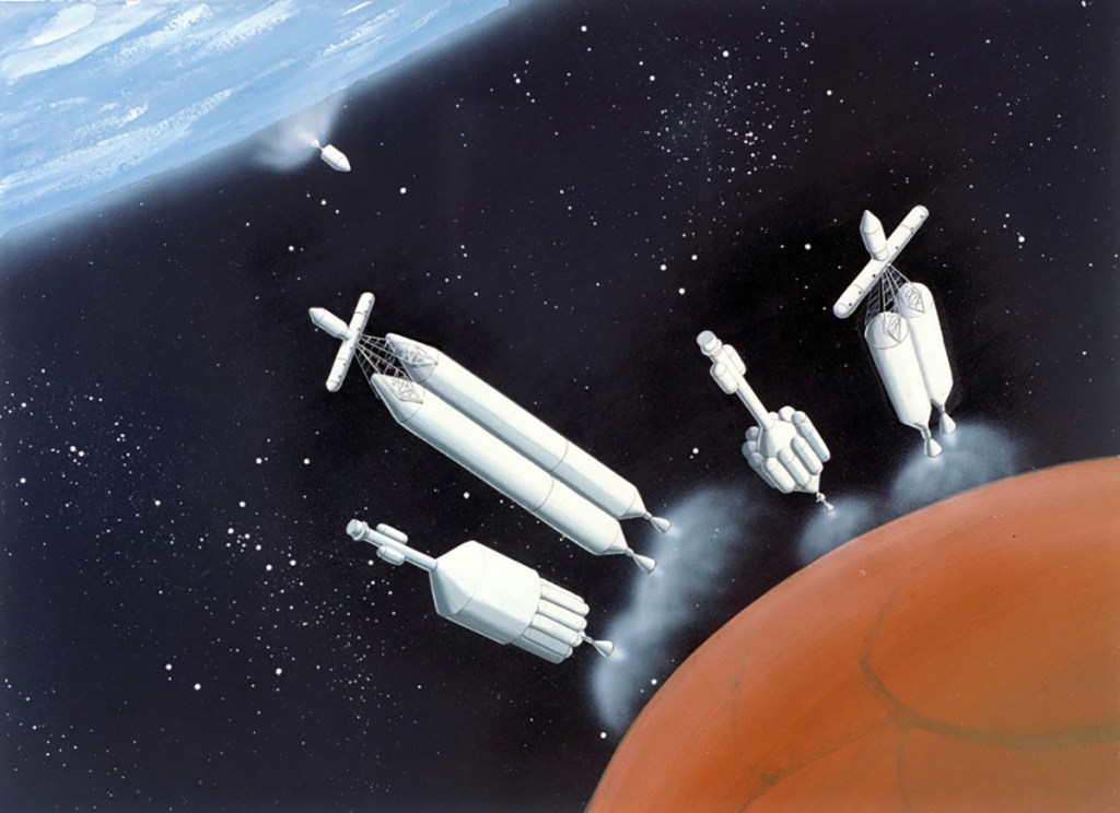
Image credit: General Dynamics / Astronautics
Image source: SDASM Archives
Image credit: General Dynamics / Astronautics
Image source: SDASM Archives