Image credit: Grumman
Image source: National Archives
Image credit: Grumman
Image source: National Archives
Image credit: Northrop
Image source: National Archives
Image credit: NASA
Image source: National Archives
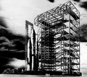
The huge Titan III C vehicle, towering over 150 feet into the air, moves into place on the launch pad. Missile is carried on same railroad car on which its parts were assembled.
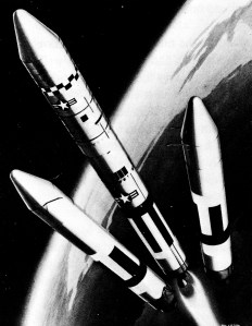
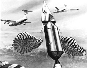
Once the solid rockets have lifted Titan III C and it’s payload off the ground, their role is finished. As this sketch shows, when the solids burn out, they separate from the core section. Just before solid burnout, the first-stage liquid propellant engines are ignited to push the spacecraft farther towards space.

Course of the Titan III and it’s payload is monitored from a launch center such as this.
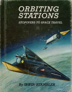
Orbiting Stations: Stopovers to Space Travel
Irwin Stambler
G.P. Putnam’s Sons, 1965
Image credit: USAF
Image source: National Archives
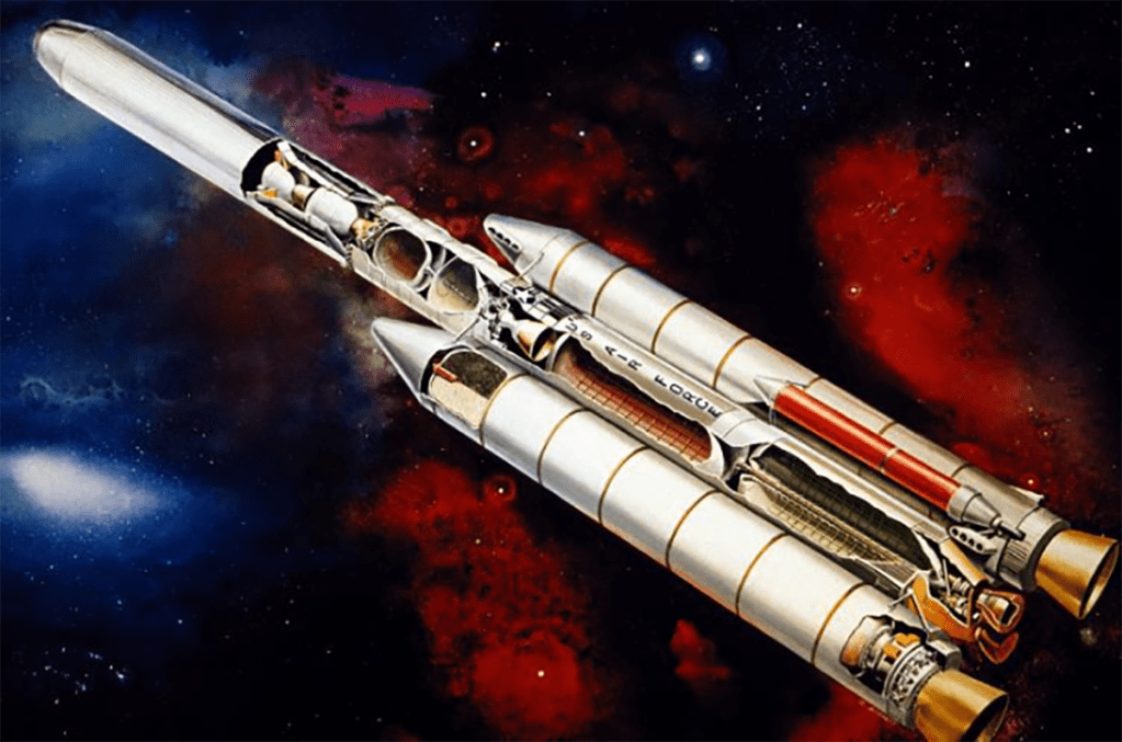
Artist’s concept of the Titan standard launch vehicle 34-D entering the space.
An artist’s concept of the new modular three-section fairing for the Air Force’s Titan III-C space launch vehicle.
Image credit: USAF
Image source: National Archives
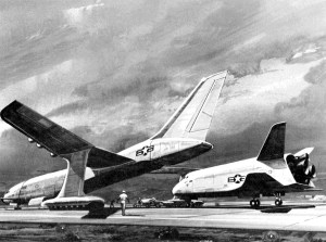
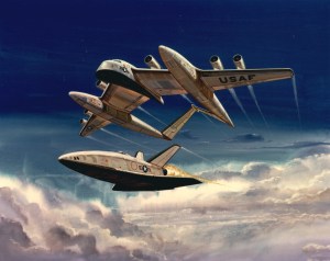
Image credit: USAF
Image source: AFMC
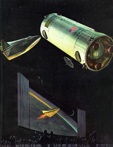
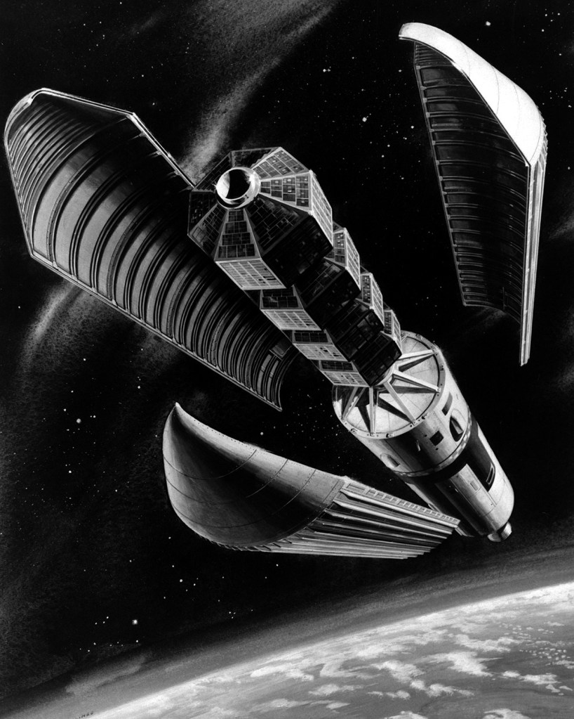
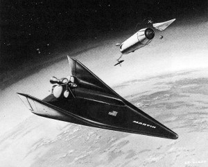
A spaceport and supply rocket designed by the Martin Marietta Corporation in mid-air in this scene from the Hall of Science space show. In such a port, astronauts may orbit for half a year.
New York World’s Fair 1964/1965
Official Souvenir Book
Time Life, 1964
Image credit: Martin Marietta
Image source: Numbers Station
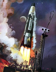
Image credit: USAF
Image source: Internet Archive
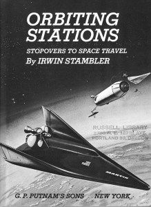
Orbiting Stations: Stopovers to Space Travel
Irwin Stambler
G.P. Putnam’s Sons, 1965
Image credit: Martin Marietta
Image source: Numbers Station
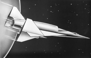
This drawing from the magazine Air Force and Space Digest shows a proposed NASA “ONE-STAGE-TO-ORBIT” aerospace plane. The craft would be able to take off from a regular airport using turbojet engines, then switch to ramjet propulsion at supersonic speed. To reach orbital speed in space, the aerospace plane would use a third set of engines using rocket propulsion.
In the drawing (above) the combination turbo-ramjet engines are housed in pods, just inside the vertical tailfins (on either side). The huge scoop atop the rear half of the fuselage contains the rocket engines and a novel collection and compression unit for gathering oxygen to burn in the rockets. The other propellant would be liquid oxygen carried in the craft’s tanks.
After it’s orbital mission, the aerospace plane would be able to reenter the atmosphere and land as a conventional aircraft at an airfield. The craft would be about 90 feet long and weigh some 100,000 pounds.
CREDIT LINE (UPI PHOTO) 7-21-62 (ML)
UNITED PRESS INTERNATIONAL ROTO SERVICE
Image credit: USAF
Image source: Numbers Station
A Lockheed artist’s impression of a novel method of taking a unique and untried method of orbital delivery and making it even more unique and more untried. As my wife said to me in the giftshop of the Palm Springs Aerial Tramway, “Baby, I’ll take the car and see you up there!”
Image credit: Lockheed
Image source: AFMC